Leave Your Message
Products Categories
Featured Products

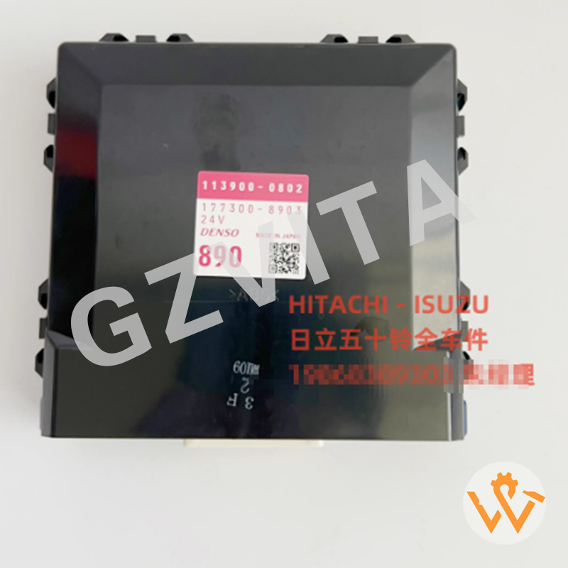
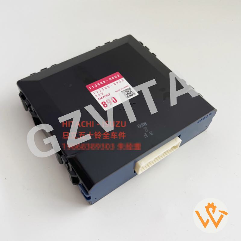
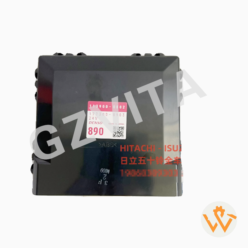
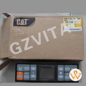
ZX200-5G ZX200-5A ZX330-5G ZX330-5A Air Conditioner Control Switch Panel YA00048010 113900-0802 177300-8903

E01​ - Engine overspeed error (RPM exceeds maximum limit).

E02​ - Engine underspeed error (RPM below minimum threshold).

E03​ - Engine speed sensor malfunction (signal abnormal).

E04​ - ECU communication error (communication with engine module lost).

E05​ - ECU internal error (processor or memory fault).

E11​ - Fuel rail pressure sensor fault (signal out of range).

E12​ - Common rail pressure abnormal (too high or too low).

E13​ - Injector circuit error (open or short circuit detected).

E14​ - Fuel temperature sensor malfunction.

E15​ - Intake air temperature sensor fault.

E16​ - Coolant temperature sensor error.

E17​ - Atmospheric pressure sensor fault.

E18​ - Boost pressure sensor error (turbocharger related).

E21​ - Camshaft position sensor malfunction.

E22​ - Crankshaft position sensor malfunction.

E23​ - Timing miscalculation error (cam/crank correlation).

E24​ - Glow plug relay control circuit error.

E25​ - Fan clutch control circuit fault.

E31​ - Battery voltage abnormal (too high or too low).

E32​ - Charging system malfunction (alternator fault).

E33​ - Power supply circuit error (to ECU or sensors).

E41​ - Throttle position sensor fault.

E42​ - Accelerator pedal sensor malfunction.

E43​ - Throttle actuator (motor) drive error.

E44​ - Throttle control system mismatch.

E51​ - CAN bus communication failure (network error).

E52​ - Display unit communication error.

E53​ - Pump controller communication loss.

E54​ - Valve controller communication loss.

E55​ - Sensor power supply voltage fault (5V reference).

E61​ - Hydraulic oil temperature sensor fault.

E62​ - Hydraulic oil level sensor malfunction.

E63​ - Hydraulic filter clogging warning.

E71​ - Swing parking brake solenoid error.

E72​ - Travel alarm circuit malfunction.

E73​ - Wiper control circuit error.

E74​ - Horn control circuit fault.

E81​ - Pump pressure sensor (P1) malfunction.

E82​ - Pump pressure sensor (P2) malfunction.

E83​ - Pump displacement sensor fault.

E84​ - Pump regulator solenoid error.

E85​ - Pump tilting angle feedback abnormality.

E91​ - Control lever sensor (front) malfunction.

E92​ - Control lever sensor (rear) malfunction.

E93​ - Pedal position sensor fault.

E94​ - Safety lock lever sensor error.

E95​ - Seat switch circuit malfunction.

E96​ - Door switch circuit error.

EA1​ - Exhaust temperature sensor fault (DPF related).

EA2​ - DPF differential pressure sensor malfunction.

EA3​ - DPF regeneration failure or interruption.

EA4​ - DEF level sensor malfunction (if equipped).

EA5​ - DEF dosing system error (if equipped).

EA6​ - NOx sensor fault (if equipped).

EB1​ - GPS/telematics communication error.

EB2​ - Security system (immobilizer) fault.

EC1​ - Monitor internal error (display memory or logic).

EC2​ - Key switch input circuit error.

ED1​ - Optional equipment communication error.

----​ - No active fault codes (system normal).

    How to Assemble the Electronic Control Group on a Tractor?

    Assembling the Electronic Control Group (ECG) on a tractor involves several steps to ensure proper installation and functionality. While the specific process may vary depending on the tractor model and manufacturer, the following general steps can guide you through the assembly process:

    1. Gather Necessary Tools and Equipment

    Ensure you have all the required tools, such as wrenches, screwdrivers, pliers, and any specialized tools recommended by the manufacturer.

    Have the Electronic Control Group components ready, including the ECU, wiring harnesses, sensors, and connectors.

    2. Refer to the Service Manual

    Obtain the tractor’s service manual or assembly guide. This document will provide specific instructions, diagrams, and torque specifications for your particular model.

    3. Prepare the Work Area

    Ensure the work area is clean and organized. Remove any debris or obstacles that could interfere with the assembly process.

    Disconnect the tractor’s battery to prevent any electrical issues during assembly.
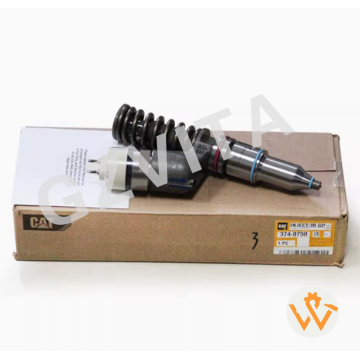
    4. Install the ECU

    Locate the designated mounting location for the ECU on the tractor. This is typically in the cabin or near the engine compartment.

    Secure the ECU in place using the appropriate mounting hardware, ensuring it is firmly attached and properly aligned.

    Leave Your Message