Leave Your Message
Products Categories
Featured Products

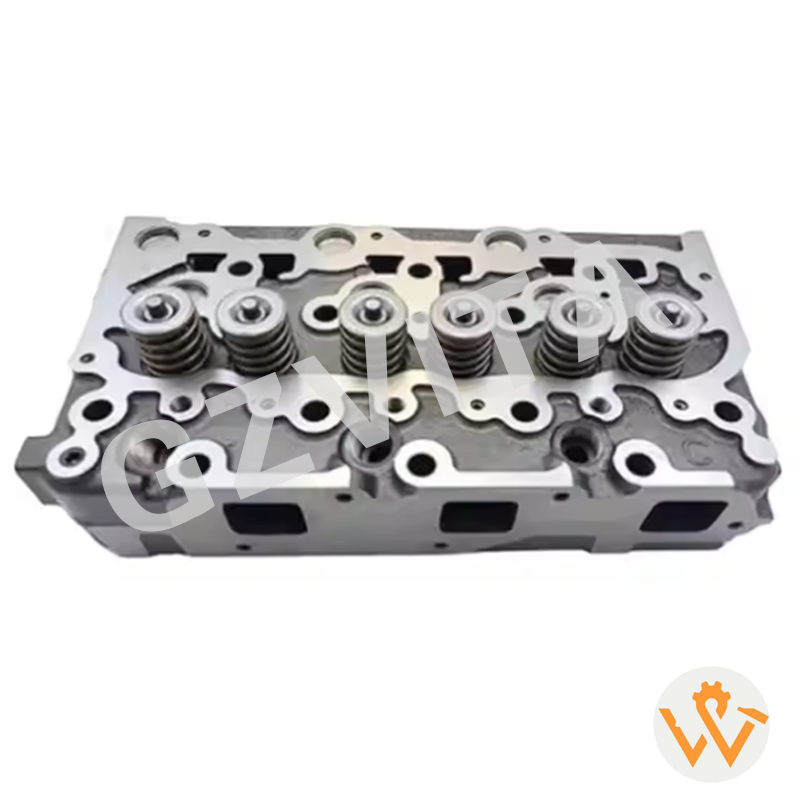
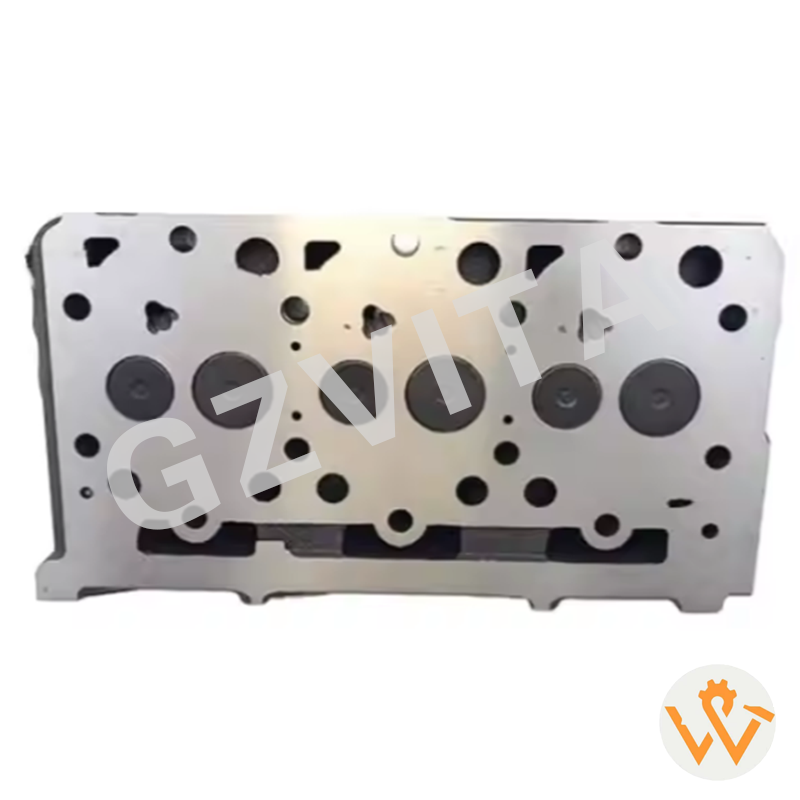
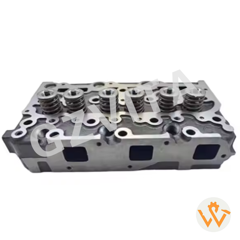
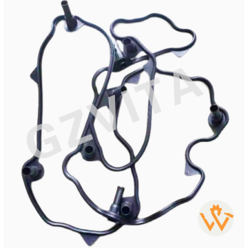
Cylinder Head 16487-03050 16444-03040 1A033-03042 for D1703 D1803 Engine

  1. Application of high-temperature resistant nickel-chromium alloys for exhaust manifolds.
  2. Use of aluminum alloy cylinder heads with advanced heat dissipation properties.
  3. Ceramic thermal barrier coatings on piston crowns to reduce heat transfer.
  4. Heat-treated forged steel for crankshafts and connecting rods for strength under thermal stress.
  5. Special high-silicon aluminum alloy for pistons to minimize thermal expansion.
  6. Stainless steel components in critical hot sections to prevent oxidation.
  7. Anodized or ceramic-coated surfaces on select parts for improved heat reflection.
  8. Use of austenitic materials in valve seats for durability.
  9. Composite metal gaskets designed to maintain seal integrity at high temperatures.
  10. Nitriding treatment on cylinder liners for enhanced wear resistance at elevated temperatures.


  1. Engine Design & Architecture


  1. Optimized combustion chamber design for efficient burning and lower peak temperatures.
  2. Cross-flow cylinder head design for improved coolant circulation around hot zones.
  3. Overhead valve (OHV) design for compactness and better heat management.
  4. Direct injection technology promoting cleaner combustion and controlled heat release.
  5. Turbocharging with intercooling to manage intake air temperature.
  6. Precision-machined components ensuring minimal friction and heat generation.
  7. Strategically placed cooling fins on air-cooled engine models.
  8. Low-friction piston rings to reduce parasitic heat from mechanical resistance.
  9. Optimized valve timing for effective scavenging and temperature control.
  10. Robust engine block design with reinforced ribbing for thermal stability.


  1. Cooling System Enhancements


  1. High-capacity, gear-driven water pumps for consistent coolant flow.
  2. Large surface area radiators with optimized core design.
  3. Thermostatically controlled coolant circulation for rapid warm-up and stable operation.
  4. Coolant bypass systems to prevent hot spots.
  5. Engine oil coolers to maintain lubricant viscosity and cooling performance.
  6. Coolant additives inhibiting corrosion and scale formation in high-heat conditions.
  7. Dual-circuit cooling systems in some industrial models for prioritized component cooling.
  8. High-efficiency cooling fans with thermally engaged clutches or viscous drives.
  9. Directed coolant jets at the bottom of pistons for under-crown cooling.
  10. Expansion tanks accommodating coolant volume changes due to temperature swings.


  1. Lubrication & Oil Management


  1. High-temperature stability engine oils meeting or exceeding specific Kubota specifications.
  2. Large-capacity oil pans providing greater heat dissipation from the oil sump.
  3. Oil jets/spray nozzles for piston cooling and lubrication.
  4. Efficient oil filters with high-temperature media to maintain cleanliness.
  5. Oil thermostats to regulate oil temperature for optimal viscosity.
  6. Bypass valve systems in oil filters for protection during cold starts or high-temperature oil thickening.
  7. Use of synthetic or semi-synthetic oils recommended for extreme operating conditions.
  8. Oil grade recommendations specifically for sustained high-load, high-temperature applications.


    How to detect the common rail for an excavator?

    Detecting the common rail injector on an excavator involves a series of steps that include visual inspection and possibly some testing.

    Here’s a guide to help you identify and check the common rail injector:

    1. Safety Precautions

    Ensure the excavator is turned off and parked on a flat surface.

    Engage the parking brake and wear appropriate personal protective equipment (PPE).

    2. Locate the Common Rail Injector

    Consult the Manual: Refer to the operator’s manual for the specific model of the excavator.

    It will provide diagrams and information on the location of the common rail injector.

    Visual Inspection: The common rail injectors are typically located on the engine’s cylinder head. Look for a rail (the common rail) that runs along the injectors, with each injector connected to it.

    3. Identify the Components

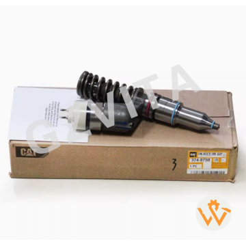
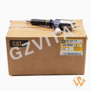
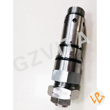
    Common Rail: This is a high-pressure rail that supplies fuel to the injectors. It is usually made of metal and has fuel lines connected to it.

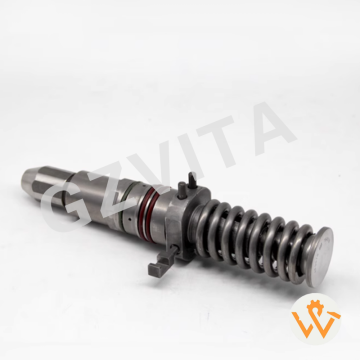
    Injectors: The injectors will be mounted on the cylinder head, with electrical connectors and fuel lines attached to them.

    4. Inspect the Injectors

    Check for Leaks: Look for any signs of fuel leakage around the injectors and the common rail.

    Electrical Connections: Ensure that the electrical connectors to the injectors are secure and free of corrosion.

    5. Testing the Injectors

    Use a Multimeter: To check the electrical resistance of the injectors, disconnect the electrical connectors and use a multimeter to measure the resistance. Compare the readings to the specifications in the manual.

    Injector Balance Test: If you have access to diagnostic equipment, perform an injector balance test to check the performance of each injector.

    Check for Fault Codes: Use a diagnostic scanner to check for any fault codes related to the fuel system or injectors.

    6. Listen for Operation

    When the engine is running, listen for any irregular sounds that may indicate injector issues, such as knocking or excessive noise.

    7. Consult a Professional

    If you are unable to diagnose the issue or if the injectors need replacement, it may be best to consult a qualified mechanic or technician.

    Leave Your Message