 +86 18578756148


0102030405
Products
01
view
detail
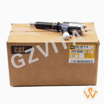
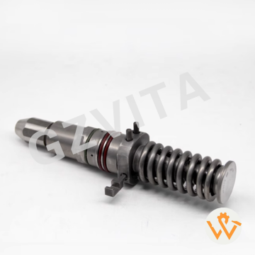
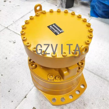
PC300-7 PC400-7 swing motor 706-7K-01070 706-7K...
2025-12-10
The Komatsu PC360-7 swing motor typically features an axial piston design with a rotating cylinder block, slipper pads, swashplate, integrated parking brake, and a multi-stage planetary gear reduction assembly.
02
view
detail
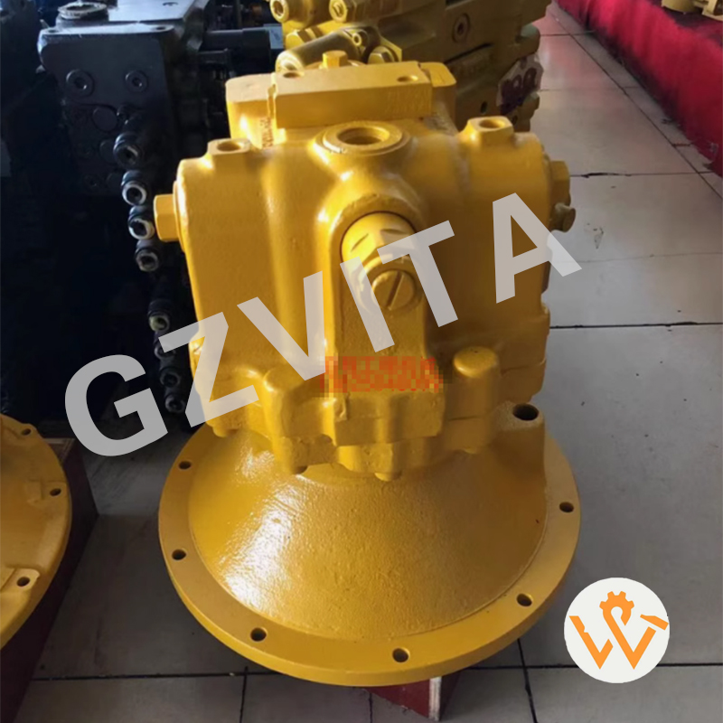
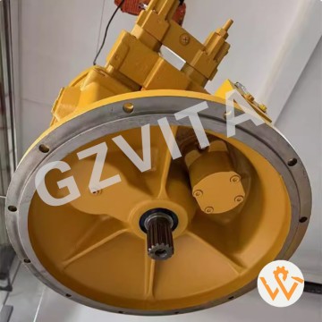
Brand New 330C 330CL Excavator Main Pump 311-95...
2025-12-10
Daily visual inspection for external leaks, , or damage on the pump housing and lines.
Check hydraulic oil level in the tank before starting the engine each shift.
Monitor hydraulic oil temperature gauge; avoid prolonged operation above normal range.
Listen for abnormal pump noises like cavitation (whining) or knocking during operation.
Inspect pump drive coupling for wear, cracks, and proper alignment.
Ensure pump mounting bolts are tight and secure to prevent vibration damage.
Verify all hydraulic hose connections at the pump are leak-free and not rubbing.
Check the pump's case drain line for unrestricted flow and no excessive leakage.
Maintain correct oil cleanliness by monitoring filter indicators and changing filters as required.
Use only recommended hydraulic oil with the proper viscosity grade for the ambient temperature.
Avoid running the pump dry – always ensure the system is primed with oil.
Allow a brief warm-up period at low idle in cold weather before applying full load.
Do not operate with a clogged or restricted inlet (suction) line or filter.
Monitor system pressure gauges for sudden drops or erratic readings.
Check for excessive heat on the pump housing by touch (caution: may be hot).
Keep the pump and surrounding area clean from dirt, mud, and debris buildup.
Follow the recommended oil change intervals strictly to maintain oil properties.
Bleed air from the hydraulic system after any service that may have introduced air.
Operate within the pump's specified pressure and flow ratings; avoid constant operation at relief pressure.
Avoid sudden and extreme changes in pump load or direction where possible.
Inspect the pump servo control linkage (if equipped) for smooth, free movement.
Ensure the hydraulic tank breather is clean and unclogged.
Record pump operation hours for accurate preventive maintenance scheduling.
Shut down immediately and investigate if a sudden loss of power or unusual vibration occurs.
Use a laser thermometer periodically to spot-check pump housing temperature.
Verify proper function of the main system relief valve as part of periodic checks.
Protect the pump from direct water jets during cleaning.
Follow the correct start-up and shutdown procedures as per the operator's manual.
Train operators to recognize early signs of potential pump problems.
Consult the official Caterpillar 330C service manual for all specific procedures, specifications, and safety warnings.
03
view
detail
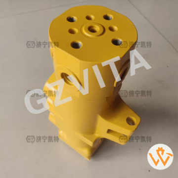
Construction Machinery Parts 703-08-00110 Swive...
2025-12-10
Centrifugal separation – Spins oil at high speed to separate contaminants by density.
Rotor assembly – The core rotating component that creates centrifugal force.
Hydraulic drive – Powered by pressurized hydraulic oil from the main system.
Jet nozzle drive – Oil jets impact rotor fins, causing rotation.
High rotational speed – Typically reaches 6000 RPM or more.
Centrifugal force generation – Creates forces hundreds of times greater than gravity.
Density-based separation – Heavier particles and water are thrown outward.
Sludge accumulation chamber – Collects separated contaminants on the inner rotor wall.
Clean oil return – Purified oil flows back to the reservoir through the center.
Continuous operation – Runs whenever the main hydraulic system is operating.
No replaceable filter element – Maintenance involves cleaning the accumulated sludge.
Efficiency indicator – Some models have a clogging indicator or speed sensor.
Rotor brake tool – Special tool to stop the rotor for disassembly during maintenance.
Rotor nut wrench – Specific socket for removing the rotor retaining nut.
Cleaning tools – Brushes and non-abrasive scrapers for removing sludge.
Balancing requirement – The rotor must be clean and balanced for smooth operation.
Dual-stage filtration – Often works in parallel with a standard pressure filter.
Fine particle removal – Effective for particles as small as 1-3 microns.
Water removal capability – Separates free and emulsified water from the oil.
Flow restrictor orifice – Controls the oil flow rate through the centrifuge.
Bypass valve – Protects the system if the centrifuge becomes blocked.
Transparent cover (optional) – Allows visual inspection of rotor operation.
Mounting bracket – Securely mounts the unit to the machine frame.
Inlet/outlet port identification – Critical for correct plumbing during installation.
Pressure test point – For verifying proper inlet pressure.
Service interval – Based on operating hours or indicated contamination level.
Rotor inspection – Check for wear, scoring, or imbalance during cleaning.
O-ring/seal kit – For replacing all seals during reassembly.
Torque specification tool – Torque wrench for the rotor nut to precise specification.
Performance verification – After service, confirm smooth, vibration-free operation at idle.
05
view
detail
Excavator for SY55U 60 65 Hydraulic Pump Assemb...
2025-12-10
Use only recommended hydraulic oil with proper viscosity and cleanliness.
Maintain oil temperature within the specified operating range (e.g., 30-70°C).
Ensure effective filtration to prevent contamination from entering the system.
Prime the pump properly before initial start-up to avoid dry running.
Avoid prolonged operation at maximum pressure settings to reduce wear.
Monitor for abnormal noises (cavitation, knocking) during operation.
Check for external leaks regularly at seals, connections, and casing.
Verify proper drive alignment to prevent bearing and shaft damage.
Allow a gradual warm-up period in cold environments before full load.
Maintain correct reservoir oil level to prevent pump cavitation.
Bleed air from the system thoroughly after maintenance or oil changes.
Follow correct start/stop procedures to minimize pressure spikes.
Avoid sudden directional or load changes where possible.
Inspect mounting bolts periodically to ensure they are tight and secure.
Protect the pump from extreme vibration through proper installation.
Use a pressure gauge to monitor system performance against specifications.
Do not exceed the maximum rated speed (RPM) for the pump.
Ensure the pump case drain line is unobstructed and routed correctly.
Implement a regular oil analysis program to monitor fluid condition.
Shut down immediately if a sudden loss of pressure or flow occurs.
Keep the pump and surrounding area clean from dirt and debris.
Operate within the pump's specified displacement and pressure envelope.
Ensure all control linkages (if equipped) move freely without binding.
Avoid moisture ingress into the hydraulic system.
Use recommended flushing procedures when changing oil types.
Follow proper storage procedures if the pump is to be out of service.
Label all hydraulic lines during disassembly for correct reassembly.
Apply thread sealant correctly on fittings to prevent leaks and contamination.
Train operators on basic pump function and alarm indicators.
Adhere strictly to the manufacturer's (Hengli) maintenance schedule and instructions.
06
view
detail
Wholesale V2607 Relay 1K533-65662 1K53365662 fo...
2025-12-10
Electrical remote switch – Acts as a remotely controlled switch for high-current circuits.
Low-current control of high-current loads – Allows a small switch/ECU signal to control heavy electrical devices.
Circuit protection – Protects sensitive control switches from high-amperage damage.
Load isolation – Separates control circuits from power circuits.
Signal amplification – Electromechanically amplifies a small input signal to handle large output power.
Power distribution hub – Centralizes switching for multiple high-power accessories.
Starter motor engagement – Controls the high-current circuit to the starter solenoid (main relay).
Fuel shutoff solenoid operation – Powers the solenoid to open/close the fuel supply.
Glow plug activation – Manages high current to glow plugs for cold starts.
Engine cooling fan control – Switches power to the electric cooling fan motor.
Fuel pump operation – Powers the electric lift pump (if equipped).
AC compressor clutch engagement – Controls power to the air conditioning clutch.
Heater fan/blower control – Switches power to the cabin heater fan.
Engine ECU main power supply – Provides switched battery power to the Engine Control Unit.
Sensor power supply – May provide stable power to critical sensors.
Pre-heater grid control – For engines with intake air heaters.
Warning light and alarm activation – Powers visual/audible alerts.
Instrument cluster power – Supplies power to gauges and displays.
Normally open (NO) contact – Contacts close to complete the circuit when energized.
Normally closed (NC) contact – Contacts open to break the circuit when energized.
Single-pole, single-throw (SPST) – A simple on/off switch configuration.
Single-pole, double-throw (SPDT) – Switches between two output circuits.
Electromagnetic coil activation – An energized coil creates a magnetic field to pull contacts.
Latching relay function – Some remain in position after a pulse signal.
Time-delay function – Certain relays have built-in timers (e.g., for glow plugs).
Continuous duty vs. intermittent duty – Rated for constant or short-term operation.
Overload protection – Prevents wiring and switches from overheating.
Short circuit protection – Often used in conjunction with fuses.
Voltage spike suppression – May contain diodes to protect control circuits.
Electrical noise reduction – Isolates noise from high-current devices.
Safety interlock implementation – Ensures sequences (e.g., start only in neutral).
Fail-safe operation – Defaults to a safe state (e.g., fuel shutoff) if power is lost.
Preventing starter motor damage – Ensures starter disengages after engine starts.
Thermal protection – Some have internal breakers to prevent overheating.
ECU command execution – The ECU triggers relays to activate actuators.
Ignition switch signal interpretation – Converts key position into power distribution.
Safety switch integration – Interrupts relay coil based on seat, PTO, or brake switches.
Timer module integration – Works with timer modules for glow plug or start sequences.
Diagnostic trigger – A faulty relay can help isolate electrical faults.
Power sequencing – Ensures systems energize in correct order (e.g., ECU before sensors).
Load shedding function – May cut non-essential loads during cranking.
Voltage stabilization – Provides a stable power source for sensitive electronics.
07
view
detail
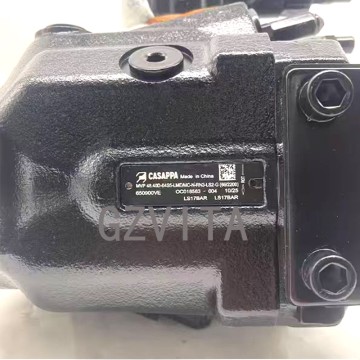
Excavator Parts: Hengli HP3V75D Main Pump Plung...
2025-12-10
Constant Flow/Pressure Regulation – Maintains steady output despite load changes.
Pressure Compensation Mechanism – Adjusts pump displacement based on system pressure.
Load-Sensing Control – Detects load demand to modulate flow and pressure.
Variable Displacement Design – Changes piston/swashplate angle to alter output.
Feedback Loop System – Uses pressure signals to continuously adjust pump delivery.
Swashplate Angle Control – Tilts the swashplate to vary piston stroke length.
Hydraulic Servo Control – Employs hydraulic pressure to position the swashplate.
Pressure Cut-off Function – Limits maximum pressure by reducing displacement.
Flow Control Valve Integration – Works with valves to stabilize flow rate.
Constant Power Regulation – Adjusts output to stay within a set power curve.
Pressure Feedback Line – Senses load pressure to guide pump adjustment.
Stable Torque Output – Maintains consistent hydraulic power to the system.
Reduced Energy Consumption – Delivers only needed flow/pressure, minimizing waste.
Automatic Destroking – At peak pressure, reduces displacement to near zero.
Compensator Spring Adjustment – Sets the desired pressure or flow level.
Spool Valve Operation – Shifts to direct control oil to the servo piston.
Servo Piston Movement – Acts on the swashplate to change displacement.
Closed-Loop Control – Continuously compares actual output with target setpoint.
Pressure Limiter Role – Prevents system overpressure by overriding other controls.
Flow Demand Matching – Supplies precise flow required by actuators.
Minimizes Heat Generation – Avoids excess fluid bypass, reducing thermal load.
Improves System Efficiency – Optimizes output to match real-time demands.
Mechanical-Hydraulic Feedback – Uses mechanical linkage for simple, reliable control.
Electro-Proportional Control (advanced) – Uses solenoid valves for precise electronic adjustment.
Maintains Actuator Speed – Keeps actuator speed constant under varying loads.
Prevents Motor Overload – Protects the drive motor by limiting hydraulic power.
Integrated Control Package – Combines compensation, pressure relief, and control in one unit.
Adaptive Output Characteristic – Automatically shifts between constant flow and constant pressure modes.
System Stability Enhancement – Reduces pressure spikes and fluctuations.
Core of Energy-Saving Hydraulics – Fundamental component for efficient modern hydraulic systems.
08
view
detail
Original Excavator Hydraulic Swing Motor for CA...
2025-12-10
Axial piston design - Utilizes pistons arranged parallel to the drive shaft axis.
Swashplate mechanism - A tilted plate converts piston reciprocation into shaft rotation.
Variable displacement - Swashplate angle can be changed to alter piston stroke and flow.
Hydraulic motor - Converts hydraulic fluid pressure and flow into rotary mechanical power.
High-torque, low-speed motor - Designed to directly drive the swing gear without a speed reducer.
Two-port operation - Features an "A" port and "B" port for forward and reverse flow.
Pressure differential - Rotation is created by applying higher pressure to one port.
Swing brake valve - An integrated valve to hold the upper structure stationary.
Mechanical parking brake - Spring-applied, hydraulically released fail-safe brake.
Pressure relief valves - Protects the motor from excessive inlet or case pressure.
Cross-port relief valves - Limits torque by allowing flow between high and low-pressure sides under shock loads.
Case drain port - Returns internal leakage oil to the tank to prevent seal damage.
Slipper pads - Attached to piston ends, they ride on the swashplate surface.
Cylinder block - Rotating component containing the piston bores.
Valve plate - Stationary part with porting to direct fluid to and from the piston chambers.
Check valves - In the brake release circuit to maintain brake piston pressure.
Anti-cavitation function - Relief valves or makeup valves prevent void formation during deceleration.
Counterbalance valves - Often used in the external circuit to prevent uncontrolled swing.
Pilot-operated check valves - Locks fluid in the motor to hold position securely.
Shaft rotation - Output shaft is splined to connect to the swing pinion gear.
Displacement control - Swashplate angle is controlled by a servo piston (in variable models).
Servo piston - A small hydraulic piston that moves the swashplate.
Control valve linkage - Mechanically connects the operator's lever to the servo control.
Port timing - The valve plate is precisely machined to align ports with piston chambers.
Pressure feedback - Some systems use load pressure to adjust displacement for power limiting.
Hydraulic braking - Motor can act as a pump during deceleration, converting inertia into heat.
Gerotor-type flushing valve - Manages case drain flow and cooling.
Smooth start/stop - Achieved through metered flow and brake valve timing.
Swing priority system - Diverts hydraulic flow to the swing circuit when commanded.
Load-independent flow control - Maintains a constant swing speed regardless of load.
Tapered roller bearings - Supports the output shaft under heavy radial and axial loads.
Piston seals - Dynamic seals that contain pressure within the piston bores.
Case pressure limitation - Critical to prevent shaft seal blow-out and housing damage.
Swing drift prevention - Tight internal clearances and holding valves minimize upper frame creep.
Thermal expansion compensation - Designed clearances account for component heating.
Pressure intensification prevention - Proper circuit design avoids trapped oil pressure spikes.
Efficiency optimization - Designed for high volumetric and mechanical efficiency.
Shock load absorption - The hydraulic fluid and relief valves cushion sudden load impacts.
Rotation direction - Determined by which port receives pressurized flow.
Speed control - Governed by the flow rate from the main control valve.
Torque output - Proportional to the displacement and the applied pressure differential.
Power input - Calculated as flow rate times pressure drop across the motor.
Kinetic energy dissipation - During braking, inertia is converted to heat in the hydraulic oil.
09
view
detail
Oil Dipstick for Mitsubishi 4M40 Engine Used in...
2025-12-10
Rated power output (e.g., 110 kW @ 3000 rpm)
Maximum torque output (e.g., 380 Nm @ 1800 rpm)
Power band characteristics - Optimal operating RPM range
Gross power rating - Factory bench test performance
Net power rating - Installed in vehicle with all accessories
SAE certified power - Standardized testing specification
Continuous duty rating - Sustained power output capability
Intermittent duty rating - Short-term peak power capacity
ISO 3046 rated power - International standard measurement
Governor-controlled maximum - Speed-regulated power limit
Altitude derated power - Reduced output at high elevation
Thermal derating consideration - Power reduction at high ambient temperatures
Fuel-specific power output - Performance per fuel type (diesel)
BMEP (Brake Mean Effective Pressure) - Cylinder pressure power indicator
BSFC (Brake Specific Fuel Consumption) - Fuel efficiency at given power
Power-to-weight ratio - Performance efficiency metric
Turbocharged power enhancement - Forced induction contribution
Intercooler efficiency effect - Charge air cooling impact on power
Injection timing optimization - Fuel system tuning for power
Pump calibration specification - Fuel delivery settings for rated power
Dyno-tested verification - Dynamometer confirmed output
Manufacturer's declared power - Official published specification
WOT (Wide Open Throttle) power - Full load performance curve
Partial load characteristics - Power delivery at intermediate throttle
Transmission-matched power - Optimized for specific gearbox pairing
Auxiliary load deducted power - Net output after alternator/AC etc.
Emissions-compliant power - Certified output meeting regulations
Service-aged power retention - Maintained performance over lifespan
Altitude compensation capability - Turbo system's elevation adaptation
Application-specific tuning - Varied ratings for excavator/truck/generator use
10
view
detail
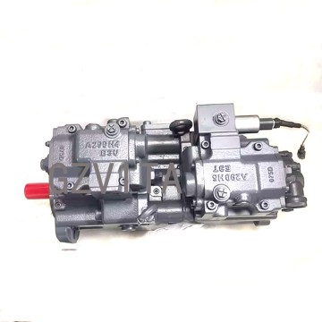
Sany35 Sy35 Hydraulic Pump 6509002R Excavator P...
2025-12-08
|

11
view
detail
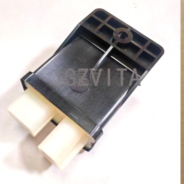
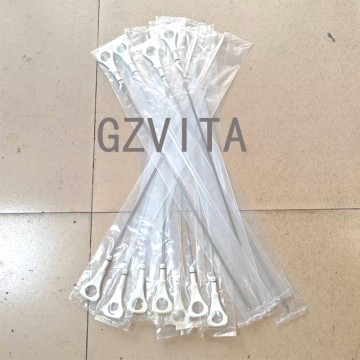
Sany Excavator Fuel Tank Cover Cap For Sany 55 ...
2025-03-19
|
1.Product name:Fuel Cap |
|
2.Part number: |
|
3.Compatible for: Sany 55 65 75 85 95 135 155 215 365 485 |
|
4.Leading time:In stock |
|
5.Packing way:Neutral packing |

12
view
detail
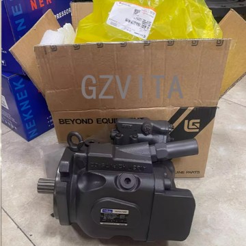
Hydraulic Pump HP5V28 For Sany 16 18 Piston Pump
2025-06-30
|
1.Product name:Hydraulic Pump |
|
2.Pump number:HP5V28 |
|
3.Compatible for: Excavator Sany 16 18 19 XCMG 15 17 |
|
4.Leading time:2-3 Days |
|
5.Packing way:Wooden Case |

13
view
detail
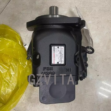
Piston Pump V90N130VRE1 For SY195 205C 215C
2025-06-27
|
1.Product name:Piston Pump |
|
2.Pump number:V90N130VRE1/BJKOGM-T2G2 |
|
3.Compatible for: Excavator XCGM 200 SY195 205C 215C |
|
4.Leading time:2-3 Days |
|
5.Packing way:Wooden Case |