How to Choose the Right Bucket Cylinder?
Choosing the right Bucket Cylinder is not a simple matter of matching bore size. It requires a careful look at machine weight, bucket capacity, working pressure, stroke length, and mounting space. A cylinder that appears powerful in a catalogue may perform poorly when the linkage geometry is unsuitable.
Hydraulic specialist Brendan Casey states, “Keep hydraulic oil clean, cool, and dry.” This practical advice matters because contamination can score the piston rod, damage seals, and reduce lifting force. Even a well-designed Bucket Cylinder can fail early when water, dust, or overheated oil enters the system.
Begin with the machine’s actual working conditions. Measure the existing cylinder, including retracted length, extended length, pin diameter, and port position. Check the bucket’s digging resistance, not only its empty weight. Rocky soil creates sharp shock loads. Wet clay may demand steady force over a longer stroke.
Small details matter.
Material selection deserves attention, too. Chrome-plated rods resist corrosion, while properly hardened pins reduce wear around the mounting eyes. Double-check the seal package for temperature and oil compatibility. This step is often rushed.
There is no universal “strongest” cylinder. Oversizing may increase stress on the boom, pins, and hydraulic pump. Undersizing may cause slow movement, leakage, or repeated rod bending. I have seen specifications treated as perfect, although field conditions later proved otherwise.
A reliable choice balances force, speed, durability, service access, and total operating cost. Before ordering, compare manufacturer drawings, pressure ratings, and warranty terms. When uncertainty remains, ask a qualified hydraulic engineer to verify the load calculations and installation measurements.
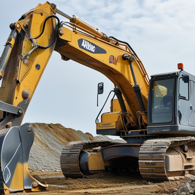
Define Bucket-Cylinder Duty: Load, Stroke, Bore, and 250–350 bar Pressure
Choosing the right bucket cylinder starts with defining its duty, not its catalog size. Record the bucket load, material density, linkage geometry, and expected digging resistance. A full bucket of wet soil can behave very differently from a light load of loose gravel. Include breakout force and impact loading, because static weight rarely tells the whole story.
Measure the required stroke from the bucket’s fully curled position to its dumping angle. A few extra millimeters may improve movement, but excessive stroke can reduce clearance or expose the rod. Bore diameter controls pushing force, while rod diameter affects buckling resistance and pulling force. Check both directions. They are not equal.
For systems operating at 250–350 bar, calculate force from effective piston area and actual working pressure. Do not select a cylinder from pressure alone. Verify hose ratings, fittings, seals, mounting pins, and the machine’s relief-valve setting. Side loads can damage the rod even when pressure remains acceptable. Oil temperature also changes seal behavior and response speed. A field shortcut is to match the old bore and stroke, but that can hide worn linkage or altered loads. I would recheck the geometry. Small errors become expensive under pressure. Test the cylinder through slow, unloaded movement before applying material, then inspect pin alignment and leakage after working cycles.
Match Stroke, Mounts, and Retracted Length to Bucket Kinematics
How to Choose the Right Bucket Cylinder?
A bucket cylinder must match the machine’s actual kinematics, not only its rated force. Measure the bucket pin center, cylinder pin center, and fully retracted length. Then map the cylinder’s stroke through the complete curl and dump arcs. A longer stroke can increase bucket rotation, but it may also cause rod-end contact or structural interference. The Grand View Research Hydraulic Cylinders Market Report 2024 valued the global market at about USD 15 billion in 2023. That scale reflects broad demand, yet it does not replace field measurements. I have seen installations fail because the cylinder fit the drawing, but not the final linkage position.
Bore and rod diameter should support the required breakout force and bending resistance. Check force at the weakest angle, often near the bucket’s digging position. Verify the retracted length against the boom, linkage, and mounting brackets. Allow clearance for hose movement and pin misalignment. ISO 4413 recommends controlling hydraulic energy and preventing unintended movement during servicing. This matters when a cylinder reaches its mechanical limit before the bucket does. I would also recheck pressure assumptions. Rated pressure is not always working pressure.
Tips: Build a simple pin-to-pin motion model before ordering. Compare three positions: fully curled, level, and fully dumped. Record real measurements twice. Small errors matter. If the cylinder nearly reaches full extension, reconsider the design rather than forcing the fit.
Apply ISO 6020/2 Dimensions, Seal Types, and Hydraulic Material Standards
How to Choose the Right Bucket Cylinder?
A bucket cylinder should match the machine’s geometry, load, and hydraulic pressure. ISO 6020/2 provides standardized mounting dimensions for medium-duty hydraulic cylinders. Check bore diameter, rod diameter, stroke length, and mounting style before comparing suppliers. Small errors matter. A cylinder with the wrong closed length can limit bucket movement or overload the linkage.
Seal selection deserves equal attention. The piston seal controls internal leakage, while the rod seal protects against pressure loss and contamination. Add a wiper seal when mud, dust, or water reaches the rod regularly. Seal materials must suit the hydraulic fluid, temperature range, pressure, and sliding speed. Polyurethane may resist abrasion well, but another elastomer could perform better with certain fluids. Compatibility charts remain necessary.
Material quality also affects service life. Choose a honed cylinder tube with documented strength and surface finish. The piston rod should have suitable hardness, corrosion resistance, and a controlled surface roughness. Request material certificates and pressure-test records when reliability matters. Confirm that the assembly follows the required hydraulic material and manufacturing standards. In field inspections, seal damage often comes from contamination, not excessive pressure. That finding is easy to overlook. Recheck alignment, filtration, and mounting loads before blaming the cylinder.
Check Rated Pressure, Rod Buckling, and a 1.25× Design Safety Margin
How to Choose the Right Bucket Cylinder?
Check Rated Pressure, Rod Buckling, and a 1.25× Design Safety Margin
A bucket cylinder must match the machine’s real hydraulic pressure, not only its advertised capacity. Check the cylinder’s rated working pressure, maximum pressure, and test pressure separately. The relief valve setting should not exceed the weakest component in the circuit. An experienced technician also checks pressure spikes during digging, especially when the bucket strikes hard soil or rock. Numbers on a drawing can look reassuring.
Rod buckling deserves equal attention. A fully extended rod carries greater risk under compression, particularly with a long stroke or heavy bucket load. Measure the distance between mounting pins, then assess rod diameter, unsupported length, and side loading. Bent pins, worn bushings, and uneven linkage alignment can increase bending forces. I have seen a cylinder fail early because the load looked acceptable, but the rod was slightly misaligned. Small errors matter.
Use a 1.25× design safety margin as a practical baseline for calculated load and pressure. For example, a 20,000-newton working load should be checked against at least 25,000 newtons, after considering friction and impact. This margin is not universal. Severe shock, frequent cycles, or poor maintenance may require a higher factor. Confirm calculations with cylinder drawings, load charts, and qualified engineering review. Do not rely on appearance alone. A thicker rod is not automatically safer if the mount or pin is weaker.
How to Choose the Right Bucket Cylinder?
Compare each cylinder’s pressure capacity and rod-buckling capacity with the design demand.
A selection passes the screening check when both capacity-to-demand ratios are at least
1.25.
Pressure ratio = rated pressure ÷ required operating pressure. Buckling ratio =
calculated Euler buckling load ÷ design compressive rod load. The values are generic
engineering screening examples; final selection should also verify stroke, mounting geometry,
pin loads, side loading, hydraulic efficiency, and applicable design standards.

 +86 18578756148
 CONTACT NUMBER
 CONTACT NUMBER
 CONTACT NUMBER

 CONTACT NUMBER