Leave Your Message
Products Categories
Featured Products

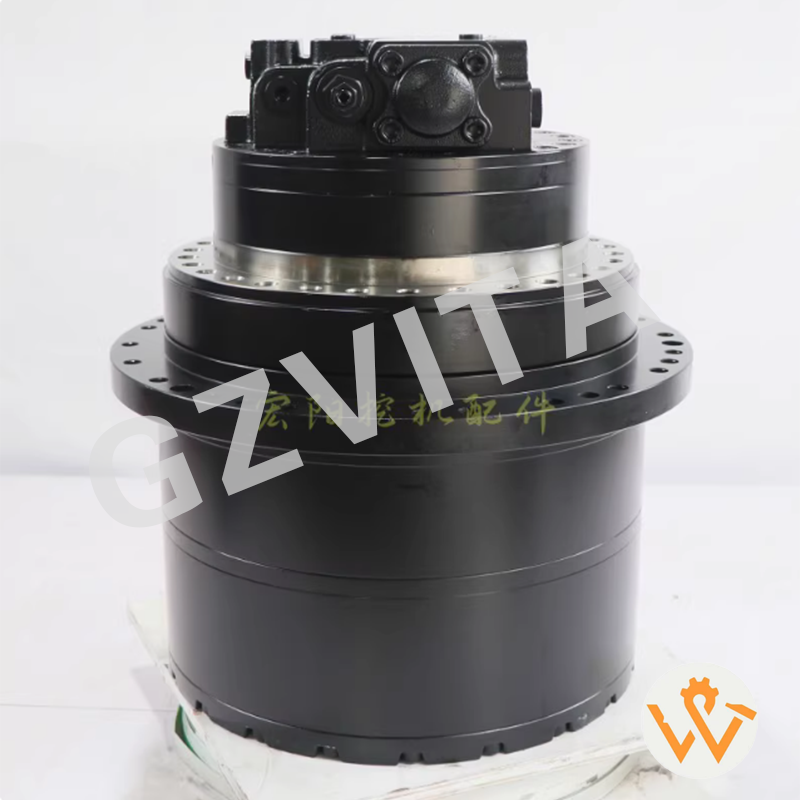
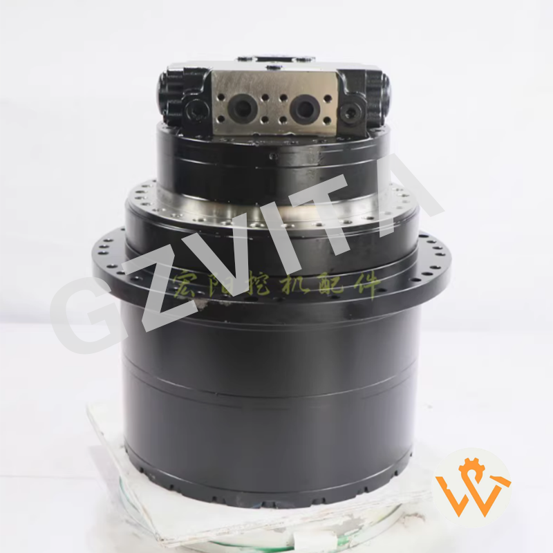
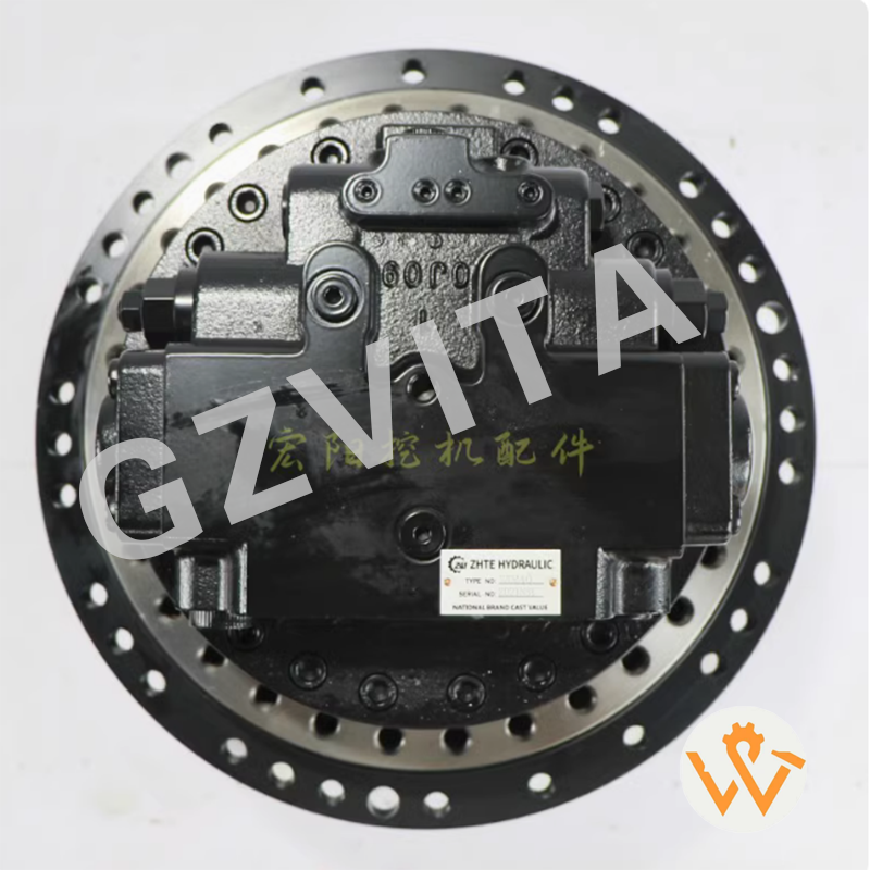
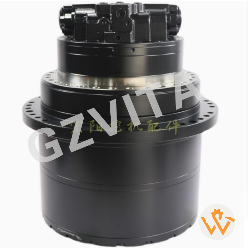
TM40 Final Drive 31N6-40050 Final Drive With Travel Motor SY215 SY235 DH225 R220 GM35 MAG-170VP-3400-7 Final Drive Assy travel reduction gearbox

Daily visual inspection – Check for external leaks, damage, or loose connections.

Monitor hydraulic oil level and cleanliness – Ensure proper oil quality and quantity.

Check final drive oil level – Verify oil level in the reduction gearbox.

Listen for unusual noises – Grinding, knocking, or whining sounds indicate issues.

Inspect mounting bolts – Ensure all fasteners are tight and secure.

Monitor travel performance – Note any slipping, uneven movement, or loss of power.

Check for overheating – Touch the motor housing (safely) after operation.

Inspect breathers and vents – Ensure they are clean and unclogged.

Examine travel chains and sprockets – Look for excessive wear or misalignment.

Verify track tension – Proper tension reduces stress on the motor.

Avoid sharp turns on hard surfaces – Minimize stress on the travel system.

Prevent contamination – Keep the area around seals and connections clean.

Operate smoothly – Avoid sudden starts, stops, or direction changes.

Check case drain flow – Ensure minimal leakage from the drain port.

Monitor system pressure – Abnormal pressure may indicate motor or pump issues.

Inspect electrical connections – For electrically controlled motors, check wiring.

Lubricate external linkages – Grease pivot points as per manual.

Avoid continuous high-speed travel – Especially on inclines or rough terrain.

Check parking brake function – Ensure it holds securely on slopes.

Inspect anti-rotation devices – Ensure they are intact and functional.

Record operating hours – Schedule maintenance based on service intervals.

Use correct hydraulic oil – Follow manufacturer’s viscosity and grade recommendations.

Bleed air from the system – If the motor feels spongy or weak.

Check alignment with final drive – Misalignment causes premature wear.

Monitor for oil contamination – Metal particles in oil indicate internal wear.

Inspect seal surfaces – Look for scratches or damage that could cause leaks.

Avoid overloading – Do not exceed the machine’s travel capacity.

Keep travel paths clear – Remove debris that could jam the tracks or sprockets.

Train operators – Ensure proper use and early problem recognition.

Follow manufacturer’s maintenance schedule – Adhere to recommended service intervals for oil changes, filter replacements, and inspections.

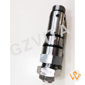
    The component for JCB distribution valve assembly

    The distribution valve assembly for JCB equipment is an essential component in the hydraulic system, responsible for directing hydraulic fluid to various functions of the machine, such as the boom, bucket, and other attachments. Here are the key components typically found in a JCB distribution valve assembly:

    Valve Body: The main housing that contains the internal components and passages for hydraulic fluid.

    Spool Valves: These are movable components within the valve body that control the flow of hydraulic fluid to different circuits. They can be shifted to direct fluid to specific functions.

    Actuators: These components are used to operate the spool valves, often controlled by levers or joysticks in the operator’s cab.

    Seals and O-rings: These are used to prevent hydraulic fluid leaks and maintain pressure within the system.

    Ports and Connectors:

    These are the entry and exit points for hydraulic fluid, connecting the distribution valve to the hydraulic lines leading to various machine functions.

    Pressure Relief Valve:

    This component helps protect the hydraulic system from excessive pressure by diverting fluid back to the reservoir when necessary.


    Return Line:

     A pathway for hydraulic fluid to return to the reservoir after it has completed its work.

    Mounting Bracket:

    This secures the distribution valve assembly to the machine frame.

    Leave Your Message