 +86 18578756148


0102030405
Products
01
view
detail
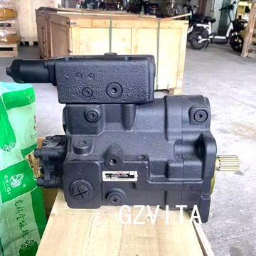
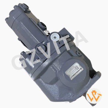
ZX65 Hydraulic Pump PVK-3B-725-N-5074A Piston M...
2025-12-13
| 1.Product name:Hydraulic pump/Main pump |
| 2.Pump number:PVK-3B-725 4668462 |
| 3.Compatible for:ZAX60 ZAX65 EX60 EX75 EX75UR |
| 4.Leading time:1-3 days |
| 5.Packing way:Wooden Case (Neutral packing) |
02
view
detail
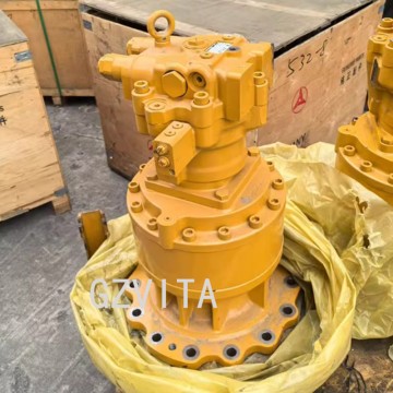
Excavator Parts Swing Reducer Slewing Motor SY2...
2025-12-13
| 1.Product name:Slewing Motor |
| 2.Pump number:M9F180A GS140D |
| 3.Compatible for:SY245 SY265 |
| 4.Leading time:1-3 days |
| 5.Packing way:Wooden Case (Neutral packing) |
03
view
detail
Hydraulic Main Pump Assembly PSVD2-17E PSVD2-17...
2025-12-13
|
1.Product name:Hydraulic pump |
|
2.Pump number:PSVD2-17E B0600-16023 |
|
3.Compatible for:VIO35 VIO40 VIO50 VIO55 |
|
4.Leading time:2-3 days |
|
5.Packing way:Wooden Case |
04
view
detail
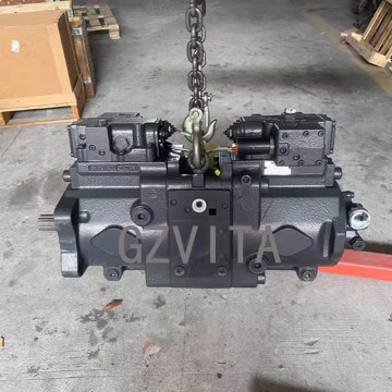
K3V112DTP-9TDL-14T Hydraulic Main Pump for Exca...
2025-12-13
|
1.Product name:Hydraulic pump |
|
2.Pump number:K3V112DTP |
|
3.Compatible for:SK200-6E SK260-6E |
|
4.Leading time:1-3 days |
|
5.Packing way:Wooden Case |
05
view
detail
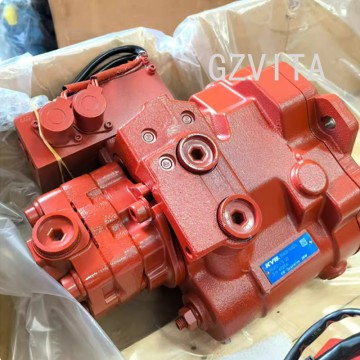
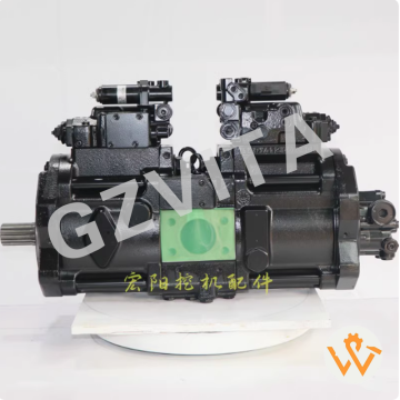
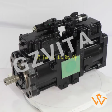
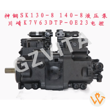
Excavator Hydraulic Pump Factory K3V63DTP-OE02 ...
2025-12-13
|
1.Product name:Hydraulic pump |
|
2.Pump number:K3V63DTP |
|
4.Leading time:2-3 days |
|
5.Packing way:Wooden Case |
07
view
detail
Hydraulic Piston Pump K3v80 11C3115 for Lingong...
2025-12-13
| 1.Product name:Hydraulic pump/Main pump |
| 2.Pump number:K3v80 11C3115 |
| 3.Compatible for:Mini Excavator CLG9075E Sunward80E9 |
| 4.Leading time:2-3 days |
| 5.Packing way:Wooden Case (Neutral packing) |
08
view
detail
Original Excavator Parts ZAX60 ZAX65 Main Pump ...
2025-12-12
Daily visual inspection – Check for external leaks, cracks, or damage.
Monitor hydraulic oil level – Ensure it is within the recommended range before operation.
Check oil temperature – Avoid operation beyond the specified temperature limit.
Listen for abnormal noises – Unusual sounds may indicate cavitation or internal wear.
Inspect pump mounting bolts – Ensure they are tight and secure.
Verify drive coupling condition – Look for wear, cracks, or misalignment.
Check suction lines and filters – Prevent restrictions or air ingress.
Monitor system pressure – Use gauges to detect abnormal fluctuations.
Inspect case drain line – Ensure it is unobstructed and not leaking excessively.
Maintain oil cleanliness – Change filters regularly and use clean oil.
Avoid dry running – Always prime the pump before starting.
Warm up the system – Operate at low pressure and flow in cold conditions.
Prevent contamination – Keep the reservoir and fill area clean.
Check for overheating – Monitor pump housing temperature during operation.
Avoid prolonged operation at maximum pressure – Reduce stress on the pump.
Inspect hoses and fittings – Look for wear, leaks, or loose connections.
Verify proper belt tension – For belt-driven pumps, ensure correct tension.
Monitor oil condition – Look for discoloration, foam, or contamination.
Check for air in the system – Bleed air if foaming or erratic operation occurs.
Ensure adequate ventilation – Prevent heat buildup around the pump.
Follow manufacturer’s operating limits – Adhere to pressure and flow specifications.
Use recommended hydraulic oil – Follow viscosity and grade requirements.
Avoid sudden pressure spikes – Operate controls smoothly to prevent shocks.
Inspect electrical connections – For electric-driven pumps, ensure secure wiring.
Record operating hours – Schedule maintenance based on service intervals.
Check alignment – Ensure the pump is properly aligned with the drive source.
Monitor pump vibration – Excessive vibration may indicate imbalance or wear.
Test relief valve function – Verify proper pressure relief during operation.
Keep maintenance records – Document inspections, repairs, and part replacements.
Train operators – Ensure they understand proper pump operation and early warning signs of failure.
09
view
detail
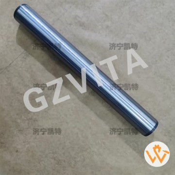
22B-70-21910 Upper Boom Cylinder Pin for PC110/...
2025-12-10
The Komatsu pin is typically made of high-carbon alloy steel, surface-hardened through carburizing or induction, with core toughness for heavy-duty impact resistance.
10
view
detail
Hydraulic Pump Assembly Parts K7V125DTP-8N01 fo...
2025-12-10
Daily visual inspection for external leaks, cracks, or damage.
Check hydraulic oil level in the main tank before each shift.
Monitor hydraulic oil temperature during operation.
Inspect oil condition for contamination, discoloration, or aeration.
Check pump drive belt for tension, cracks, and wear.
Listen for unusual noises from the pump (cavitation, whining).
Verify pump mounting bolts are tight and secure.
Inspect all hydraulic hose connections at the pump for leaks.
Check inlet (suction) line for restrictions, kinks, or air leaks.
Ensure the oil reservoir breather cap is clean and unclogged.
Monitor system pressure using gauges for abnormal readings.
Check for excessive case drain flow which indicates internal wear.
Inspect the pump shaft seal for any signs of oil leakage.
Keep the pump and surrounding area clean from dirt and debris.
Follow recommended oil change intervals using specified XCMG-grade oil.
Change hydraulic filters (suction, pressure, return) as scheduled.
Bleed air from the hydraulic system after servicing or oil changes.
Use a laser thermometer to check for abnormal pump housing temperature.
Verify proper operation of the main system relief valve.
Check for damaged or vibrating hydraulic lines near the pump.
Ensure the oil cooler is functioning to maintain optimal oil temperature.
Inspect the pump servo control linkage (if equipped) for smooth operation.
Record pump operation hours for preventive maintenance scheduling.
Avoid running the pump at full stroke/load for extended periods unnecessarily.
Use proper filtration units when adding new hydraulic oil.
Check the alignment of the pump drive coupling.
Inspect the condition of the pump's external control levers or solenoids.
Follow XCMG's specific warm-up procedure in cold weather before full operation.
Immediately investigate any sudden loss of power or slow operation.
Consult the official XCMG 245 service manual for all detailed procedures and specifications.
11
view
detail
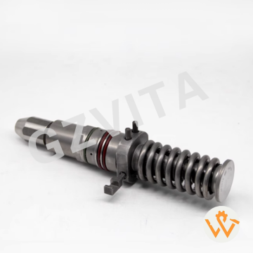
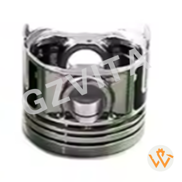
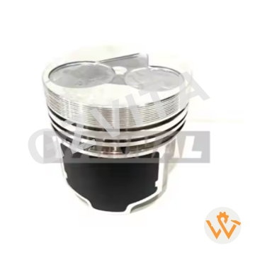
D782 3D67E-1A Piston With Pin 1G688-2111 1G688-...
2025-12-09
|
Lightly lubricate the piston pin, rod small end, and bearings with assembly lubricant before final assembly. Use a proper piston ring compressor tool that fits the bore diameter snugly to compress the rings. Tighten the compressor evenly and ensure all rings are fully compressed below the ring lands. The rod bearings must be generously lubricated with assembly lube or clean engine oil. Protect the crankshaft journal with a piece of plastic hose or a dedicated protector to prevent nicks during installation. Rotate the crankshaft so the connecting rod journal for the cylinder you are working on is at bottom dead center(BDC). Guide the rod onto the crankshaft journal carefully, ensuring the bearing shell remains in place. The piston should enter the bore with moderate, even pressure from the heel of your hand. If excessive force is needed, stop and check that rings are fully compressed. Never force or hammer a piston into the cylinder bore, as this will cause immediate and severe damage. For engines with cylinder liners, take extra care not to catch the ring compressor on the liner lip. Once the piston is started, hold the ring compressor firmly against the block as you push the piston down until the rings clear the tool. Install the rod cap in its original orientation and on its original rod (match markings must align). Ensure the bearing shell is clean, lubricated, and correctly seated in the rod cap. The rod cap bolts/nuts must be clean, undamaged, and lightly oiled on the threads and under the head. Always use new rod bolts or nuts if specified by the manufacturer; they are torque-to-yield (stretch bolts) in most modern engines. Hand-start all bolts or nuts to ensure threads are not crossed. Tighten in multiple stages and in the correct sequence (usually alternating) to the specified torque value. For torque-to-yield bolts, tighten to the initial torque spec, then angle tighten (e.g., 90°+90°) exactly as specified. Do not reuse a standard torque value. After tightening, the rod should rotate freely on the journal with slight drag from the bearing clearance. It must not be loose or bind. Use a plastic mallet to tap the rod cap sideways to ensure proper bearing crush and alignment before final torque. After installing all pistons, rotate the crankshaft by hand two full revolutions to feel for any binding or interference. After all pistons are installed, re-check the torque on all rod bolts as a final verification. Measure the rod side clearance (end play) on the crankshaft with a feeler gauge to ensure it is within specification. Verify there is no excessive up-and-down play in the rod bearing, which would indicate incorrect bearing size. Ensure all piston ring gaps remain properly staggered and have not rotated during installation. Double-check that each piston is at the same height at top dead center(TDC) if deck height is critical for compression ratio. For interference engines, perform a"clay test"or use a piston stop to physically verify there is sufficient valve-to-piston clearance. Clean any fingerprints, assembly lube, or debris from the cylinder walls and piston crowns before installing the cylinder head. Install the oil pump and prime the lubrication system before final engine assembly to ensure immediate oil flow on startup. Before initial startup, disable the fuel and ignition systems and crank the engine with the starter to build oil pressure. Follow the manufacturer's specific break-in procedure for the first start and run-in period to properly seat the rings and bearings. |
12
view
detail
D722 Engine Piston 16851-21114 16851-21113 1685...
2025-12-09
|
Cleanliness is paramount; the engine block cylinder bores, piston, and all related components must be surgically clean and free of debris. Thoroughly clean and inspect the cylinder bores for any scoring, taper, or out-of-round condition before installation. The piston ring grooves must be completely free of carbon deposits and varnish to allow rings to seat and function properly. Use a ridge reamer to remove the carbon ridge at the top of the cylinder bore from previous wear; failure to do so can damage new rings and pistons. Verify the piston-to-cylinder wall clearance with a micrometer and bore gauge, ensuring it matches the manufacturer's exact specification. Check ring end-gap for each compression and oil control ring in its respective cylinder, filing the ends if necessary to achieve the specified clearance. All connecting rods and rod bolts must be inspected for straightness, and bolts must be new or certified for reuse. Ensure the piston pin is the correct fit for the piston and connecting rod, with the specified clearance (snug slip-fit or press-fit). The wrist pin retaining clips (circlips) must be new and fully seated in their grooves. Lubricate all components liberally with assembly lube or clean engine oil immediately prior to installation to prevent dry start-up. Always install piston rings one at a time using a proper ring expander tool to avoid scratching or distorting the rings and piston. The ring markings (dots, "TOP" stamps, etc.) must face upward toward the crown of the piston, unless otherwise specified. Stagger the ring end gaps around the piston circumference as per the manufacturer's diagram (typically 120 or 180 degrees apart). Never align the ring gaps with the piston pin bore or perpendicular to it, as this is a common path for blow-by. For oil control rings, ensure the expander (spacer) ends butt together and do not overlap, and the scraper rails are correctly seated. The gap of the oil ring rails should be positioned on the opposite side of the expander gap. Double-check that rings move freely in their grooves without binding after installation. Ensure the ring side clearance (between the ring and the groove) is within specification using a feeler gauge. For performance engines, always follow the specific ring manufacturer's gap and orientation instructions, which may differ from OEM. Never roll the rings onto the piston from the side; this can permanently twist or damage the rings. Identify the front of the piston (usually marked with an arrow, notch, or "FRONT"). The piston must be installed with the front mark facing the front of the engine (towards the timing cover). For offset piston pins, ensure the correct side faces the major thrust side of the cylinder wall (typically marked or specified). Verify the connecting rod and cap are matched pairs and installed in their original cylinder; they are not interchangeable. Rod bearing shells must be the correct size and properly seated in the rod and cap, with locating tabs engaged. The bearing bore in the rod and cap must be spotlessly clean and dry before inserting the bearing shell. When pressing the wrist pin, use a proper fixture and controlled press to ensure alignment and prevent distorting the rod. Always install new piston pin retaining circlips and ensure they are fully seated in the groove all around. For full-floating pins, ensure the pin moves freely and install new spiral locks or circlips as specified. |

13
view
detail
Kubota Excavator U15 Idler Undercarriage parts ...
2025-03-12
|
1.Product name:Excavator Idler |
|
2.Part number: |
|
3.Compatible for: Kubota U15 |
|
4.Leading time:2-3 days |
|
5.Packing way:Wooden Case |
14
view
detail
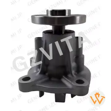
Water Pump 15424-73034 15425-73037 For Kubota E...
2025-02-20
|
1.Product name:Water Pump |
|
2.Part number:15424-73034 15425-73037 |
|
3.Compatible for:Kubota Engine V1512 D725 |
|
4.Leading time:2-3 days |
|
5.Packing way:Neutral packing or customization packing |
15
view
detail
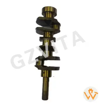
1G065-23010 Crankshaft Compatible For Kubota Di...
2025-02-20
|
1.Product name:Crankshaft |
|
2.Part number:1G065-23010 16265-23013 |
|
3.Compatible for:D1105 Engine |
|
4.Leading time:2-3 days |
|
5.Packing way:Neutral packing or customization packing |
16
view
detail
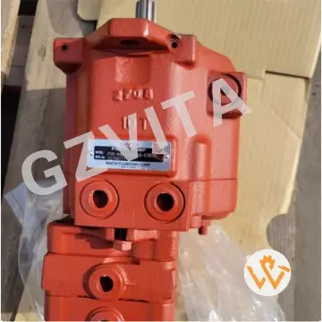
PVD-00B-14P Main Pump For Kubota Excavator U15 ...
2025-02-20
|
1.Product name:Hydraulic pump |
|
2.Pump number:PVD-00B-14P |
|
3.Compatible for:Kubota U15 U17 |
|
4.Leading time:2-3 days |
|
5.Packing way:Wooden Case |