 +86 18578756148


0102030405
Products
01
view
detail
Excavator Parts 329FL Hydraulic Pump 3390514 33...
2025-12-11
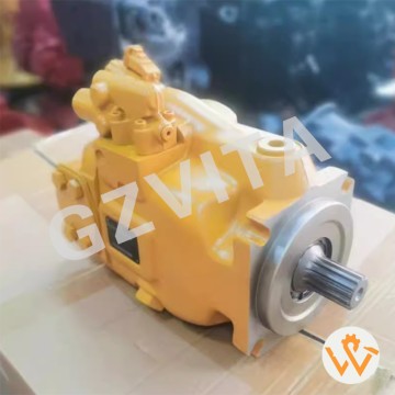
Variable displacement axial piston pumps (dual).
Load sensing pressure-flow compensated (LSPC) system.
Swashplate angle control for output adjustment.
Hydraulic or electro-hydraulic servo control.
Closed-center load sensing (CLSS) circuit.
Power sharing between pumps.
Pressure cut-off (PCO) function.
Horsepower matching with the engine.
Cross-sensing between pump sections.
Displacement feedback mechanism.
High-pressure rotating groups.
Stationary valve plates.
Integral charge pump for make-up flow.
Case drain and flushing circuit.
Main system relief valves.
Anti-cavitation check valves.
Pressure compensator valves.
Flow compensator valves.
Load signal network (LS lines).
Pilot pressure supply circuit.
Pump controller (electronic or hydraulic).
Proportional solenoid valves (if equipped).
Pressure transducers for control feedback.
Mounting and drive system to the engine.
Breather and case drain ports.
Filtration system for charge and case drain oil.
Temperature management via case drain flow.
Efficiency optimization logic.
Fail-safe pressure and flow limiting.
Integrated diagnostic capability.
02
view
detail
SBS120 SBS-120 E320D Hydraulic Pump 397-3680 Hy...
2025-12-11
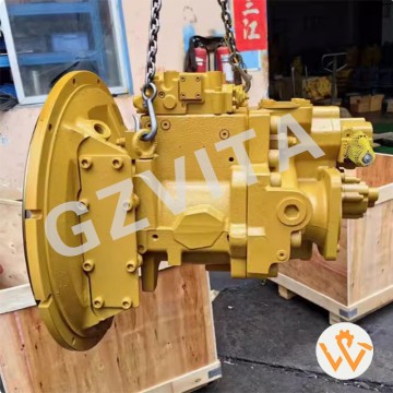
Variable displacement axial piston pumps (dual).
Load sensing pressure-flow compensated (LSPC) system.
Swashplate angle control for output adjustment.
Hydraulic or electro-hydraulic servo control.
Closed-center load sensing (CLSS) circuit.
Power sharing between pumps.
Pressure cut-off (PCO) function.
Horsepower matching with the engine.
Cross-sensing between pump sections.
Displacement feedback mechanism.
High-pressure rotating groups.
Stationary valve plates.
Integral charge pump for make-up flow.
Case drain and flushing circuit.
Main system relief valves.
Anti-cavitation check valves.
Pressure compensator valves.
Flow compensator valves.
Load signal network (LS lines).
Pilot pressure supply circuit.
Pump controller (electronic or hydraulic).
Proportional solenoid valves (if equipped).
Pressure transducers for control feedback.
Mounting and drive system to the engine.
Breather and case drain ports.
Filtration system for charge and case drain oil.
Temperature management via case drain flow.
Efficiency optimization logic.
Fail-safe pressure and flow limiting.
Integrated diagnostic capability.
04
view
detail
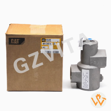
4N-3411 4N3411 Relay Valve for Caterpillar GENE...
2025-12-11
One-way flow control
Backflow prevention
Coolant system protection
Lube oil pressure maintenance
Fuel supply line check
Air intake anti-backflow
Exhaust system pressure retention
Starting air system safety
Jacket water circuit direction control
Aftercooler circuit protection
Turbocharger oil supply protection
Crankcase ventilation control
Fuel injection pump protection
Coolant deaeration system function
Water pump cavitation prevention
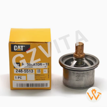
Thermostat bypass regulation
Coolant heater circuit control
Header tank overflow prevention
Cooling system priming aid
Emergency shutdown system function
Coolant filter bypass protection
Deaeration tank inlet control
Aftertreatment system protection
Hydraulic starter circuit control
Crankcase breather system check
Pre-lube system pressure retention
Fuel transfer pump protection
Coolant additive injection control
System pressure stabilization
Emergency coolant circulation control
05
view
detail
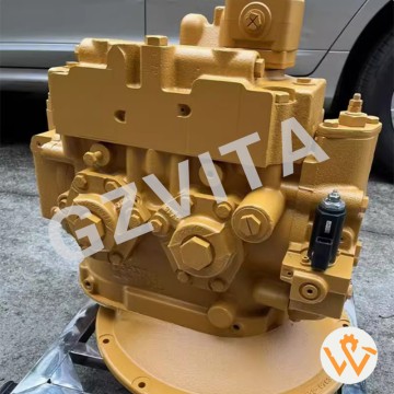
SBS120 Hydraulic Main Pump E320DL Hydraulic Pum...
2025-12-10
Variable displacement axial piston pumps (likely dual).
Load sensing pressure-flow compensated (LSPC) system.
Swashplate angle control for output adjustment.
Hydraulic or electro-hydraulic servo control.
Closed-center load sensing (CLSS) circuit.
Power sharing between pumps.
Pressure cut-off (PCO) function.
Horsepower matching with the engine.
Cross-sensing between pump sections.
Displacement feedback mechanism.
High-pressure rotating groups.
Stationary valve plates.
Integral charge pump for make-up flow.
Case drain and flushing circuit.
Main system relief valves.
Anti-cavitation check valves.
Pressure compensator valves.
Flow compensator valves.
Load signal network (LS lines).
Pilot pressure supply circuit.
Pump controller (electronic or hydraulic).
Proportional solenoid valves (if equipped).
Pressure transducers for control feedback.
Mounting and drive system to the engine.
Breather and case drain ports.
Filtration system for charge and case drain oil.
Temperature management via case drain flow.
Efficiency optimization logic.
Fail-safe pressure and flow limiting.
Integrated diagnostic capability.
06
view
detail
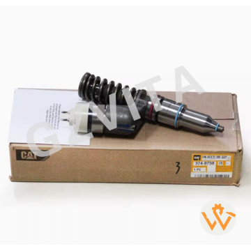
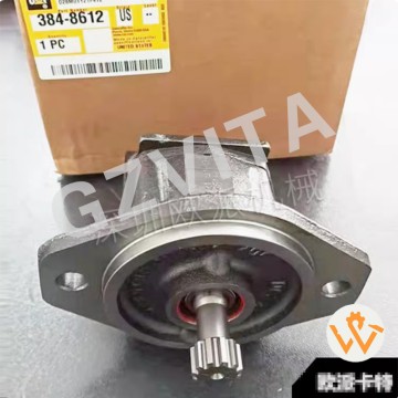
384-8612 Fuel Transfer Pump for CAT C11 C13 C15...
2025-12-10
Common Rail fuel injection system (ACERT engines)
High-pressure fuel rail storing fuel at constant pressure
Electronic Control Module (ECM) managing injection parameters
High-pressure fuel pump generating system pressure
Cam-driven plungers creating pumping action
Pressure control valve regulating rail pressure
Fuel rail pressure sensor providing feedback to ECM
Electronic unit injectors with solenoid control
Precise injection timing controlled by ECM
Multiple injection events per cycle (pilot/main/post)
Variable injection pressure up to 2000+ bar
Supply pump feeding high-pressure pump
Fuel temperature sensor for density compensation
Injection duration control by ECM signals
Crankshaft position sensor for timing reference
Camshaft position sensor for cylinder identification
Fuel pressure limiter for system protection
Fuel cooler managing return temperature
Leak-off circuit returning excess fuel
Pressure relief valve emergency protection
Two-stage filtration before injection pump
Electric priming pump (if equipped)
Adaptive pressure control based on load
Cold start strategy with increased pressure
Diagnostic monitoring of all parameters
Torque limitation through fuel control
Idle speed control via injection timing
Cylinder balancing through individual trim
Fail-safe modes for limp-home operation
CAN communication with other vehicle systems

07
view
detail
Kubota Excavator KX151 155 161 Large Pump PSVL-...
2025-12-10
Closed-center load sensing (CLSS) system
Variable displacement axial piston pump(s)
Load-independent flow distribution
Pressure compensation valves for each function
Electronic proportional control (lever signals)
Pilot-operated main control valves
Independent travel circuits (left/right)
Swing motor with parking brake
Pilot pressure supply system
Hydraulic oil cooler with fan
Return line filtration
Case drain circuits for motors/pumps
Anti-cavitation valves
Cross-port relief valves (swing/travel)
Power mode selection (economy/standard)
Auto-idle function
Arm/bucket regeneration circuits
Boom holding valves
Travel speed selection (2-speed)
Swing priority function
Pilot check valves for stability
Negative flow control (NFC) or similar
Hydraulic oil temperature sensor
Electronic pump control system (if equipped)
Main relief valve(s)
Pilot relief valve
Attachment circuit (optional)
Hydraulic tank with breather
Suction line filter
Central hydraulic manifold block
08
view
detail
723-40-51102 723-40-51100 723-40-91100 91102 Ma...
2025-12-10
Maximum pressure limitation – Prevents system pressure from exceeding safe levels.
Hydraulic system protection – Protects pumps, valves, and cylinders from overpressure damage.
Pressure relief function – Diverts excess pump flow to tank when pressure reaches set point.
Load holding safety – Maintains pressure in cylinders when controls are in neutral.
Thermal management – Relieves pressure to reduce heat generation during stalling.
Shock absorption – Cushions pressure spikes from sudden load changes.
Pump unloading – Allows pump flow to return to tank at low pressure when not needed.
Energy conservation – Reduces power loss and fuel consumption by unloading the pump.
Stall prevention – Prevents engine stalling by relieving pressure at maximum setting.
Cylinder and hose protection – Prevents bursting of hoses and seals.
Stable operation – Maintains consistent system pressure for smooth machine control.
Emergency pressure release – Provides a safe pressure release path in fault conditions.
Boom and arm safety – Holds boom and arm in position without drifting.
Swing brake engagement – Maintains pressure for swing parking brake application.
Travel motor protection – Prevents overpressure in travel circuits.
Implement circuit security – Safeguards attachment hydraulic circuits.
Pilot system pressure regulation – May regulate pressure for pilot control circuits.
Sequence valve function – In some systems, directs flow based on pressure.
System pressure calibration point – Used to set and verify main system pressure.
Noise reduction – Reduces hydraulic noise by preventing excessive pressure.
Cavitation prevention – Maintains sufficient back pressure to avoid vacuum conditions.
Leakage compensation – Compensates for internal leakage in cylinders and valves.
Load sensing system integration – Works with load sensing pumps to control flow.
Multi-function valve operation – May have multiple relief settings for different functions.
Thermal relief capability – Opens at lower pressure if oil temperature is too high.
Anti-shock valve coordination – Works with anti-shock valves to dampen shocks.
Electric override capability – Some models have solenoid-controlled unloading.
Manual override provision – For emergency operation or testing.
Pressure adjustment capability – Can be adjusted to match different working conditions.
System diagnostics indicator – Abnormal pressure readings can indicate other system faults.
09
view
detail
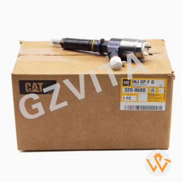
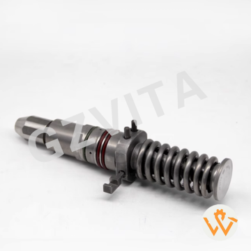
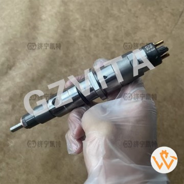
Proman 6745-12-3100 6745123100 INJECTOR Applica...
2025-12-10
Fuel atomization – Breaks diesel into fine mist for efficient combustion.
Precise fuel metering – Delivers exact fuel quantity as commanded by ECU.
Injection timing control – Injects fuel at precisely the right moment in the cycle.
High-pressure fuel delivery – Operates at common rail pressure (1600-2500 bar).
Multiple injection capability – Performs pilot, main, and post injections.
Solenoid or piezoelectric actuation – Electrically controlled needle valve opening.
Hydraulic amplification – Uses fuel pressure to assist needle valve movement.
Rapid response time – Opens and closes in milliseconds or microseconds.
ECU command execution – Receives and executes injection commands from Engine Control Unit.
Spray pattern formation – Creates optimal spray shape for air-fuel mixing.
Penetration control – Controls how far fuel penetrates into combustion chamber.
Combustion noise reduction – Pilot injection softens combustion onset.
Emission reduction – Optimized injection reduces NOx and particulates.
Pressure maintenance – Seals high-pressure fuel when closed.
Leak-free closure – Prevents after-drip and nozzle dribbling.
Needle valve control – Precisely lifts and seats the needle.
Control chamber pressure regulation – Uses fuel pressure to control needle.
Fuel filtration – Final barrier before injection (integrated filter).
Heat dissipation – Transfers combustion heat to fuel and engine.
Hydraulic balance design – Uses fuel pressure for both opening and closing.
Durability under extreme pressure – Withstands repeated high-pressure cycles.
Calibration data storage – Contains individual trim codes for ECU.
Cylinder-specific adaptation – Allows individual cylinder fuel adjustment.
Self-diagnostic capability – ECU monitors electrical and hydraulic function.
Cold start enhancement – Delivers precisely timed injections for easy starting.
Torque shaping – Contributes to optimal torque curve through injection control.
Idle stability control – Fine injection adjustments stabilize idle RPM.
Particulate filter regeneration support – Post-injection provides HC for DPF regeneration.
Nozzle hole optimization – Precisely machined holes for optimal flow and spray.
Critical emission control component – Essential for meeting Tier 3/4 emission standards.
10
view
detail
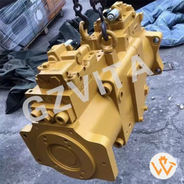
Hydraulic Main Pump 584-0379 5840379 K7V280DTP ...
2025-12-10
Axial piston variable displacement design (likely).
Two independent pump sections for dual-circuit hydraulics.
Electronic pressure/flow control (EPFC/EPR) system.
Swashplate angle control for displacement variation.
High-pressure rotating group (cylinder block, pistons, slippers).
Stationary valve plate for port timing.
Integral charge pump for case flush and pilot supply.
Pressure and flow compensator valves.
Proportional solenoid control valves (likely).
Displacement feedback sensor (e.g., resolver or RVDT).
Case drain port and flushing valve.
High-pressure relief valves (main and cross-port).
Pilot-operated control pistons for swashplate movement.
Electronic controller integration (ECM/Pump Controller).
CAN bus communication interface.
Pressure transducers on pump outlets.
Temperature sensor for oil monitoring.
Tapered roller bearings for shaft support.
Shaft seal with contamination exclusion ring.
Cast iron or ductile iron housing.
Modular design for serviceability.
Mounting flange for engine or gearbox connection.
Hydraulic displacement control pistons (servo pistons).
Anti-cavitation check valves.
Load sensing signal ports (LS system).
External drain line connections.
Anti-rotation linkage for swashplate.
Spring chambers for compensator valves.
Filtered pilot supply port.
Sealed, multi-chamber internal housing.
11
view
detail
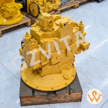
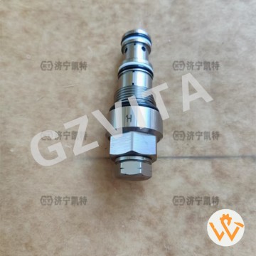
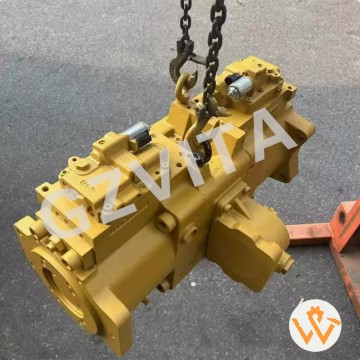
YUE CAI 352GC 349GC Excavator Main Pump 5840379...
2025-12-10
Operating pressure within specified range (e.g., 350 bar).
System flow matching pump displacement and engine RPM.
Case drain flow minimal and within manufacturer's limit.
No abnormal noise (whining, knocking, or cavitation sounds).
Smooth, vibration-free operation at all working points.
Rapid and precise response to control inputs.
Stable pressure holding when valves are in neutral.
Minimal external leakage (only slight seepage at seals acceptable).
Proper shaft seal temperature (warm, not hot to touch).
Correct pump displacement in both minimum and maximum settings.
Efficient power conversion (minimal heat generation).
Accurate pressure compensation response to load changes.
Consistent flow delivery proportional to control signal.
Proper servo control movement (for variable pumps).
Stable control current/voltage to proportional solenoids.
Correct pump drive alignment with the engine.
Minimal pressure ripple in the system.
Adequate inlet pressure (no cavitation at suction port).
Normal case pressure (typically below 2-3 bar).
No air bubbles in the return or case drain line.
Proper integration with electronic control system (if equipped).
Correct communication with the machine's main controller (CAN).
Accurate feedback signals from sensors (pressure, angle, temperature).
Optimal response time for mode changes (e.g., power modes).
No error codes related to the pump in the monitoring system.
Fuel efficiency consistent with machine specification.
Cycle times meeting the machine's performance standards.
Smooth combined operations (boom, arm, swing simultaneously).
Reliable operation across the entire working temperature range.
Performance matching the factory specification sheet for the 349GC model.
12
view
detail
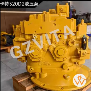
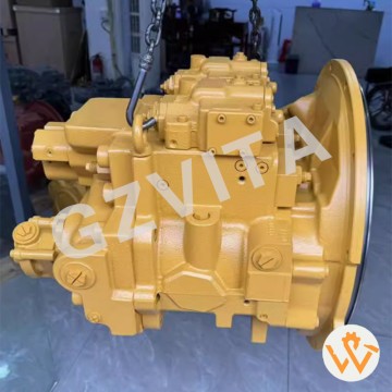
Excavator Parts 504-5477 336D2 Main Pump 336D2 ...
2025-12-10
Internal leakage – Excessive wear causing low flow/pressure.
Shaft seal failure – External hydraulic oil leakage.
Bearing wear/noise – Causing vibration and potential shaft damage.
Cavitation damage – From air ingress or restricted inlet flow.
Overheating – Due to inefficiency, high load, or poor cooling.
Pressure loss/drop – Inability to reach or maintain rated pressure.
Low flow output – Reduced machine speed and weak performance.
Erratic operation – Surging or inconsistent hydraulic action.
Unusual noise (whine/knock) – Indicating wear or cavitation.
Case drain flow excessive – Sign of severe internal wear.
Control response sluggish – Slow reaction to operator commands.
Pump housing cracks – From stress, freezing, or impact.
Coupling/shear pin failure – Due to shock load or misalignment.
Contamination damage – From abrasive particles in the oil.
Swashplate/cylinder wear – In variable displacement pumps.
Valve plate scoring – Leading to internal leakage and heat.
Slipper pad wear – Causing noise and loss of efficiency.
Servo piston sticking – In variable pumps, causing control failure.
Charge pump failure – In closed-loop systems, causing weak steering/travel.
Pressure compensator fault – Failing to maintain set pressure.
Flow compensator fault – Failing to deliver demanded flow.
Solenoid valve failure – In electronically controlled pumps.
Sensor failure (pressure/displacement) – Sending erroneous signals to controller.
Mounting bolt loosening – Causing misalignment and vibration.
Oil aeration – Pump drawing in air, causing noise and damage.
Water contamination – Leading to corrosion and reduced lubrication.
Incorrect oil viscosity – Causing poor lubrication or high resistance.
Over-pressurization – From relief valve failure, damaging internals.
Fatigue failure – Of internal components from cyclic loading.
General efficiency degradation – Gradual loss of performance and increased fuel consumption.
13
view
detail
Original Special Price Pump Assembly 487-6223 H...
2025-12-10
Daily visual inspection for leaks, cracks, or damage.
Check hydraulic oil level before startup.
Monitor oil temperature during operation.
Listen for unusual noises (cavitation, knocking).
Inspect pump drive coupling for wear and alignment.
Tighten mounting bolts to specified torque.
Check all hydraulic connections for leaks.
Inspect inlet (suction) line for restrictions or air leaks.
Ensure reservoir breather is clean and unclogged.
Monitor system pressure for abnormalities.
Check case drain flow for excessive internal leakage.
Inspect shaft seal for external leakage.
Keep pump and area clean from dirt and debris.
Use only recommended oil with correct viscosity.
Change hydraulic filters as scheduled.
Bleed air from the system after servicing.
Check oil cooler for proper function.
Inspect servo linkage (if equipped) for smooth operation.
Record pump operating hours for maintenance scheduling.
Avoid dry running – ensure system is primed.
Allow warm-up period in cold weather.
Avoid constant operation at maximum pressure.
Use a laser thermometer to spot-check housing temperature.
Check for vibration which indicates misalignment or wear.
Verify relief valve function periodically.
Follow correct start/stop procedures.
Shut down immediately if sudden power loss occurs.
Use proper filtration when adding new oil.
Train operators on basic pump monitoring.
Consult the official Caterpillar 310D service manual for all specifications and procedures.
14
view
detail
Excavator Spare Parts K5V212 Hydraulic Pump for...
2025-12-10
Internal leakage – Excessive wear causing low flow/pressure.
Shaft seal failure – External hydraulic oil leakage.
Bearing wear/noise – Causing vibration and potential shaft damage.
Cavitation damage – From air ingress or restricted inlet flow.
Overheating – Due to inefficiency, high load, or poor cooling.
Pressure loss/drop – Inability to reach or maintain rated pressure.
Low flow output – Reduced machine speed and weak performance.
Erratic operation – Surging or inconsistent hydraulic action.
Unusual noise (whine/knock) – Indicating wear or cavitation.
Case drain flow excessive – Sign of severe internal wear.
Control response sluggish – Slow reaction to operator commands.
Pump housing cracks – From stress, freezing, or impact.
Coupling/shear pin failure – Due to shock load or misalignment.
Contamination damage – From abrasive particles in the oil.
Swashplate/cylinder wear – In variable displacement pumps.
Valve plate scoring – Leading to internal leakage and heat.
Slipper pad wear – Causing noise and loss of efficiency.
Servo piston sticking – In variable pumps, causing control failure.
Charge pump failure – In closed-loop systems, causing weak steering/travel.
Pressure compensator fault – Failing to maintain set pressure.
Flow compensator fault – Failing to deliver demanded flow.
Solenoid valve failure – In electronically controlled pumps.
Sensor failure (pressure/displacement) – Sending erroneous signals to controller.
Mounting bolt loosening – Causing misalignment and vibration.
Oil aeration – Pump drawing in air, causing noise and damage.
Water contamination – Leading to corrosion and reduced lubrication.
Incorrect oil viscosity – Causing poor lubrication or high resistance.
Over-pressurization – From relief valve failure, damaging internals.
Fatigue failure – Of internal components from cyclic loading.
General efficiency degradation – Gradual loss of performance and increased fuel consumption.
15
view
detail
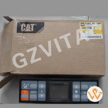
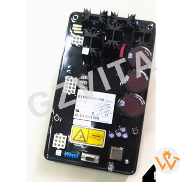
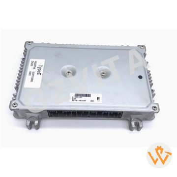
ZX200 ZX225USR ZX240-3G ZAX230 ZAX240 ECU Compu...
2025-12-10
E01 - Engine overspeed (RPM exceeds maximum limit).
E02 - Engine underspeed (RPM below minimum threshold).
E03 - Engine speed sensor malfunction (signal abnormal).
E04 - ECU communication error (communication with engine module lost).
E05 - ECU internal error (processor or memory fault).
E11 - Fuel rail pressure sensor fault (signal out of range).
E12 - Common rail pressure abnormal (too high or too low).
E13 - Injector circuit error (open or short circuit detected).
E14 - Fuel temperature sensor malfunction.
E15 - Intake air temperature sensor fault.
E16 - Coolant temperature sensor error.
E17 - Atmospheric pressure sensor fault.
E18 - Boost pressure sensor error (turbocharger related).
E21 - Camshaft position sensor malfunction.
E22 - Crankshaft position sensor malfunction.
E23 - Timing miscalculation error (cam/crank correlation).
E24 - Glow plug relay control circuit error.
E25 - Fan clutch control circuit fault.
E31 - Battery voltage abnormal (too high or too low).
E32 - Charging system malfunction (alternator fault).
E33 - Power supply circuit error (to ECU or sensors).
E41 - Throttle position sensor fault.
E42 - Accelerator pedal sensor malfunction.
E43 - Throttle actuator (motor) drive error.
E44 - Throttle control system mismatch.
E51 - CAN bus communication failure (network error).
E52 - Display unit communication error.
E53 - Pump controller communication loss.
E54 - Valve controller communication loss.
E55 - Sensor power supply voltage fault (5V reference).
16
view
detail
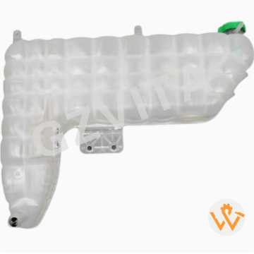
Construction Machinery Parts Water Tanks 554-94...
2025-12-10
-
Coolant volume expansion accommodation – Stores excess coolant heated by the engine.
-
System pressure regulation – Helps maintain stable pressure via the sealed cap.
-
Coolant replenishment reservoir – Provides a supply to compensate for minor system losses.
-
Air pocket elimination aid – Allows air bubbles to escape from the cooling system.
-
Coolant level visual indicator – Allows easy monitoring of system fill level.
-
Overflow collection – Captures coolant expelled if the system overheats.
-
Contamination prevention – Sealed system minimizes dirt and debris entry.
-
Coolant degassing function – Helps separate and remove trapped air from the liquid.
-
Thermal contraction buffer – Returns coolant to the radiator as the system cools.
-
Coolant aging observation point – Allows inspection of coolant color and clarity.
-
Leak detection indicator – A dropping level can signal a leak elsewhere.
-
Pressure relief protection – Works with the pressure cap to prevent overpressure damage.
-
Coolant mixing and circulation point – Where fresh coolant is typically added.
-
System bleeding reference point – Used during coolant refill and air purge procedures.
-
Reserve for evaporation loss – Compensates for gradual evaporation over time.
-
Auxiliary surge tank – Prevents coolant loss from the main radiator overflow tube.
-
Chemical reaction reservoir – Contains coolant additives and inhibitors.
-
Durability testing component – Designed to withstand underhood heat and vibration.
-
Environmental protection feature – Prevents coolant from spilling onto the ground.