 +86 18578756148


0102030405
Products

01
view
detail
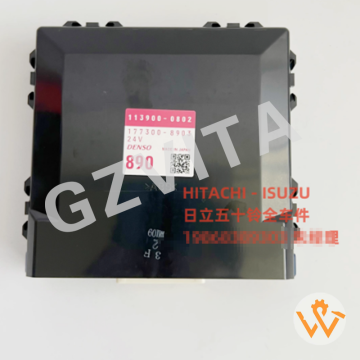
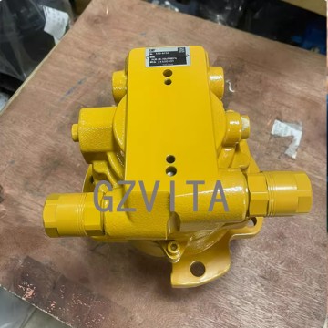
Excavator Controller PC300-8MO PC350-8MO Excava...
2025-12-10
CA111 - Pump 1 discharge pressure sensor abnormality (signal out of range).
CA112 - Pump 2 discharge pressure sensor abnormality.
CA122 - Pump 1 control current abnormality (NC/PC solenoid circuit fault).
CA222 - Pump 2 control current abnormality.
CA144 - Pump 1 tilting angle sensor abnormality.
CA244 - Pump 2 tilting angle sensor abnormality.
CA187 - Swing parking brake solenoid abnormality (current fault).
CA342 - Arm regeneration solenoid abnormality.
CA352 - Boom regeneration solenoid abnormality.
CA433 - Travel speed shift solenoid abnormality.
CA525 - Engine control communication error (data from engine ECU lost).
CA551 - CAN bus error (main controller communication fault).
CA552 - Display unit communication error (monitor communication lost).
E01 - Engine overspeed (RPM exceeds maximum limit).
E02 - Engine underspeed (RPM below minimum threshold).
E03 - Engine speed sensor abnormality (signal irregular).
E11 - Common rail pressure sensor abnormality (signal out of range).
E15 - Engine coolant temperature sensor abnormality.
E20 - Intake air temperature sensor abnormality.
E21 - Atmospheric pressure sensor abnormality.
E26 - Coolant level switch abnormality (low coolant warning).
E101 - DPF differential pressure sensor abnormality.
E102 - DPF over-temperature warning.
E103 - DPF regeneration request or failure.
E108 - Exhaust temperature sensor abnormality (DPF inlet/outlet).
E109 - DEF (diesel exhaust fluid) level sensor abnormality (if equipped).
E110 - DEF pressure sensor abnormality (if equipped).
AA10 - Fuel pre-filter warning (water detected or clogging).
HH01 - Hydraulic oil temperature sensor abnormality.
HH02 - Hydraulic oil level switch abnormality (low oil warning).
02
view
detail
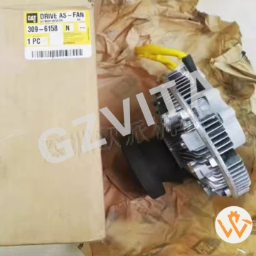
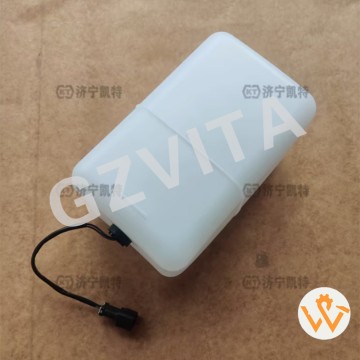
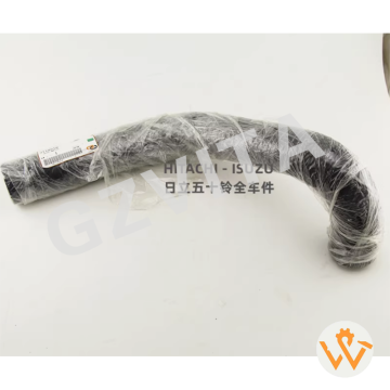
PC300-8 PC400-8 Excavator Reservoir Tank 419-03...
2025-12-10
EPDM (Ethylene Propylene Diene Monomer) rubber - Most common, excellent heat and coolant resistance.
Heat-resistant synthetic rubber compound (continuous use up to 120-140°C).
Coolant/antifreeze resistant formulation - Resists glycol-based and OAT coolants.
Ozone-resistant compound - Prevents cracking from atmospheric ozone exposure.
Flexible yet durable elastomer - Withstands vibration and minor impacts.
Aging-resistant polymer blend - Formulated for long service life underhood.
Chemical-resistant to oil and fuel splash - From incidental contact in engine bay.
Pressure-rated construction - Withstands system pressure (typically 0.5-1.5 bar).
Low-temperature flexible - Remains pliable in sub-zero conditions.
UV-stabilized outer layer - If exposed to sunlight, resists UV degradation.
Multi-layer construction - Sometimes with inner barrier layer for low permeation.
Molded-in reinforcement ribs - For structural strength and shape retention.
Molded-in mounting brackets - Integral part of the rubber housing.
Precision-molded spouts and necks - For secure hose and cap connection.
Flame-retardant additive package (some formulations).
Anti-static compound - Prevents dust attraction in some applications.
Mineral-filled compound - For cost and stiffness adjustment.
Carbon black filled - For UV protection and strength.
Peroxide-cured EPDM - For superior heat resistance over sulfur-cured.
Low-permeability liner (in some designs) - To reduce coolant vapor loss.
Synthetic rubber blend (e.g., EPDM/NBR blend) for specific properties.
Color-stable compound (typically black).
Seamless rotational molding or blow molding - For one-piece tank construction.
Molded-in sight glass or level indicator window (if applicable).
Bonded or over-molded metal inserts - For threaded fittings or brackets.
High tear strength formulation.
Resistant to coolant additive packages (silicates, nitrates, etc.).
Hydrolytically stable - Resists breakdown from hot, pressurized coolant/water.
Compatibly formulated with adjacent plastics (e.g., PP, PA) to prevent material interaction.
Manufacturer-specified OEM grade material - Meeting exact automotive/equipment durability standards.
03
view
detail
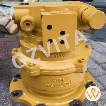
PCR-4B-20A 452-6208 452-6209 Excavator E306 305...
2025-12-10
Operate within rated torque and speed limits specified in the manual.
Allow for a brief warm-up period at low speed before heavy swing operation.
Avoid sudden, violent directional changes when starting or stopping rotation.
Do not use the swing function to pry or drag heavy objects sideways.
Minimize continuous high-speed, full-load rotation for extended periods.
Keep the gearbox mounting bolts tight and check them periodically.
Ensure the parking brake is fully released before beginning swing operation.
Listen for unusual noises (grinding, knocking) during rotation and investigate immediately.
Monitor for excessive external heat on the gearbox housing during or after use.
Check for oil leaks around seals, gaskets, and inspection covers regularly.
Maintain the correct oil level and use only the recommended oil type and viscosity.
Change the gear oil at the specified service intervals.
Keep the breather vent clean and unobstructed.
Avoid striking the lower structure (gearbox/carriage) with obstacles during swinging.
Ensure smooth engagement by operating the swing control levers gradually.
On slopes, swing with extra caution and at reduced speed to maintain stability.
Do not use the swing function to help free the machine if it is stuck; use proper recovery techniques.
After operation on slopes, engage the parking brake before releasing the controls.
Prevent contamination by keeping the area around seals and fill plugs clean during maintenance.
Inspect the swing pinion and swing bearing gear teeth for damage during scheduled maintenance.
Check for excessive backlash or play in the swing mechanism.
Follow the manufacturer’s break-in procedure for a new or rebuilt减速机.
Avoid exposing the gearbox to direct, high-pressure water jets during cleaning.
Use the machine’s auto-lubrication system (if equipped) as scheduled for the swing bearing.
Shut down and inspect immediately if a loss of swing power or control is noticed.
Do not modify or disable any safety devices related to the swing system.
Ensure the swing path is clear of personnel and obstructions before rotating.
Balance loads and avoid excessive centrifugal force from off-center heavy loads.
Follow all safe shutdown procedures, including neutralizing swing controls and engaging the parking brake.
Refer to the official Caterpillar 305.5 operation and maintenance manual for complete, model-specific instructions and warnings.
04
view
detail
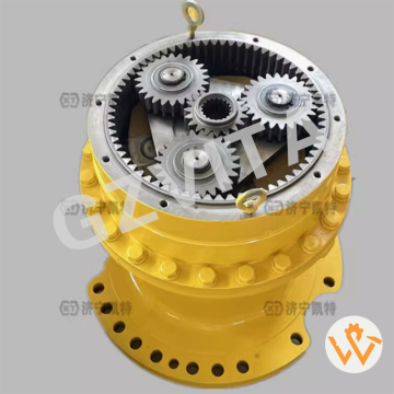
Swing Reduction Gearbox 208-26-00231 for Komats...
2025-12-10
Multi-stage planetary gear set for high torque reduction.
Central sun gear as the primary input driver.
Multiple planet gears rotating around the sun gear.
Planetary carrier assembly connecting the planet gears to the output.
Stationary ring gear (annulus) fixed to the housing.
Heavy-duty gearbox housing made of high-strength cast iron or steel.
Integral swing bearing mounting flange on the top of the housing.
Input shaft connected to the hydraulic swing motor.
Output shaft (vertical) driving the swing pinion gear.
Swing pinion gear engaging with the swing bearing gear teeth.
Tapered roller bearings supporting the planetary carrier and shafts.
Needle roller bearings for planet gear rotation.
Large cross roller bearing (swing bearing) seated above/within the assembly.
Hydraulic motor mounting flange on the input side.
Internal lubrication system with oil channels and splash lubrication.
Magnetic drain plug to capture ferrous wear particles.
Breather vent to equalize internal pressure.
Sealed housing with multiple gaskets and oil seals.
Input shaft oil seal preventing leakage at the motor interface.
Output shaft oil seal preventing leakage at the pinion interface.
Bolted inspection cover for gear and bearing access.
Heavy-duty mounting bolts securing the gearbox to the upper frame.
Internal spacer sleeves for precise bearing preload adjustment.
Shim packs for setting gear meshing backlash.
Anti-rotation lugs or keys securing stationary components.
Oil level sight glass or dipstick for lubrication monitoring.
Temperature sensor port (optional) for condition monitoring.
Cast reinforcement ribs on the housing for structural integrity.
Machined sealing surfaces for precise gasket and seal fit.
Counterweight integration – the housing itself contributes to machine balance.
05
view
detail
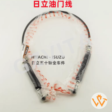
Excavator Parts ZX200 ZX200LC ZX210 ZX200-5G ZX...
2025-12-10
Engine speed control – Regulates the diesel engine's RPM.
Operator input translation – Converts lever/pedal position into a throttle command.
Mechanical linkage (if cable) – Physically connects the control lever to the fuel pump rack.
Electrical signal transmission (if electronic) – Sends throttle position voltage to the ECU.
Idle speed adjustment – Sets the minimum stable engine speed.
Maximum speed limitation – Defines the upper RPM limit for the engine.
Power mode selection – Part of the system that switches between Eco/Power modes.
Manual throttle override – Allows operator direct control independent of auto-idle.
Fuel injection pump control – Directly moves the pump's control rack (mechanical).
Work mode synchronization – Coordinates engine speed with hydraulic pump demand.
Auto-deceleration activation – Returns engine to low idle when controls are neutral.
Deceleration damper function – Prevents throttle from snapping shut abruptly.
Cruise control interface – Connects to the system for constant RPM hold.
Governor system input – Provides the operator's desired speed setting to the governor.
Cold start aid – Allows setting a slightly higher idle for warm-up.
PTO speed setting – Sets precise RPM for auxiliary hydraulic attachments.
Hydraulic pump flow matching – Adjusts engine speed to match required hydraulic flow.
Fuel efficiency optimization – Enables operator to select optimal RPM for the task.
Noise level management – Lower RPM reduces overall machine noise.
Emissions influence – Engine speed affects combustion and exhaust emissions.
Operator comfort control – Allows tailoring of engine response to preference.
Safety interlock connection – May link to seat/pressure switches.
Diagnostic monitoring point – Throttle signal is monitored for faults by the monitor.
Redundant safety feature – Mechanical cable provides backup if electronic system fails.
Precision control enablement – Allows fine adjustments for delicate operations.
Attachment compatibility – Ensures correct engine speed for specialized tools.
Machine response tuning – Affects how quickly the machine reacts to control inputs.
Bleed-off control (hydraulic) – Influences hydraulic system bleed-off valve operation.
System calibration reference – Provides a baseline signal for control system calibration.
Essential power management – A fundamental component for overall machine power and productivity control.
06
view
detail
Hot Sales ZX200-3 EXCAVATOR water hose 3104767 ...
2025-12-10
Oil-resistant synthetic rubber (NBR/HNBR)
Multi-layered textile braid reinforcement
High-tensile steel wire braid reinforcement
Abrasion-resistant synthetic rubber cover
Heat-resistant compound (up to 120°C)
Ozone-resistant outer layer
Low-temperature flexible formulation
High-pressure rated construction
Non-conductive rubber compound
Fuel-resistant tube material
Anti-weathering synthetic rubber
Anti-swelling additive package
Static dissipative variant available
SAE J1402 compliant rubber
ISO 18752 compliant material
Polychloroprene (CR) outer cover
Chlorosulfonated polyethylene (CSM) cover
EPDM rubber for certain coolant lines
PTFE inner liner for high-grade hoses
Textile reinforcement cord (polyester)
Aramid fiber reinforcement layer
Spiral steel wire reinforcement
Molded rubber end fitting seals
Heat-reflective sleeve material
Flame-retardant rubber compound
Anti-static rubber formulation
Factory-applied color coding stripes
Part number imprinting on cover
Low-permeability tube compound
Environmentally resistant polymer blend
07
view
detail
ZX200-5G ZX200-5A ZX330-5G ZX330-5A Air Conditi...
2025-12-10
E01 - Engine overspeed error (RPM exceeds maximum limit).
E02 - Engine underspeed error (RPM below minimum threshold).
E03 - Engine speed sensor malfunction (signal abnormal).
E04 - ECU communication error (communication with engine module lost).
E05 - ECU internal error (processor or memory fault).
E11 - Fuel rail pressure sensor fault (signal out of range).
E12 - Common rail pressure abnormal (too high or too low).
E13 - Injector circuit error (open or short circuit detected).
E14 - Fuel temperature sensor malfunction.
E15 - Intake air temperature sensor fault.
E16 - Coolant temperature sensor error.
E17 - Atmospheric pressure sensor fault.
E18 - Boost pressure sensor error (turbocharger related).
E21 - Camshaft position sensor malfunction.
E22 - Crankshaft position sensor malfunction.
E23 - Timing miscalculation error (cam/crank correlation).
E24 - Glow plug relay control circuit error.
E25 - Fan clutch control circuit fault.
E31 - Battery voltage abnormal (too high or too low).
E32 - Charging system malfunction (alternator fault).
E33 - Power supply circuit error (to ECU or sensors).
E41 - Throttle position sensor fault.
E42 - Accelerator pedal sensor malfunction.
E43 - Throttle actuator (motor) drive error.
E44 - Throttle control system mismatch.
E51 - CAN bus communication failure (network error).
E52 - Display unit communication error.
E53 - Pump controller communication loss.
E54 - Valve controller communication loss.
E55 - Sensor power supply voltage fault (5V reference).
E61 - Hydraulic oil temperature sensor fault.
E62 - Hydraulic oil level sensor malfunction.
E63 - Hydraulic filter clogging warning.
E71 - Swing parking brake solenoid error.
E72 - Travel alarm circuit malfunction.
E73 - Wiper control circuit error.
E74 - Horn control circuit fault.
E81 - Pump pressure sensor (P1) malfunction.
E82 - Pump pressure sensor (P2) malfunction.
E83 - Pump displacement sensor fault.
E84 - Pump regulator solenoid error.
E85 - Pump tilting angle feedback abnormality.
E91 - Control lever sensor (front) malfunction.
E92 - Control lever sensor (rear) malfunction.
E93 - Pedal position sensor fault.
E94 - Safety lock lever sensor error.
E95 - Seat switch circuit malfunction.
E96 - Door switch circuit error.
EA1 - Exhaust temperature sensor fault (DPF related).
EA2 - DPF differential pressure sensor malfunction.
EA3 - DPF regeneration failure or interruption.
EA4 - DEF level sensor malfunction (if equipped).
EA5 - DEF dosing system error (if equipped).
EA6 - NOx sensor fault (if equipped).
EB1 - GPS/telematics communication error.
EB2 - Security system (immobilizer) fault.
EC1 - Monitor internal error (display memory or logic).
EC2 - Key switch input circuit error.
ED1 - Optional equipment communication error.
---- - No active fault codes (system normal).
08
view
detail
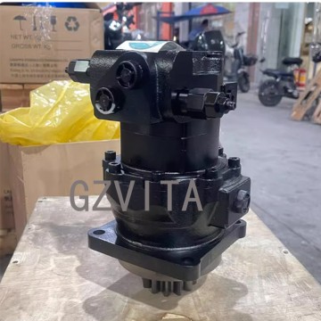
Excavator Parts LG26/27/35 Micro Excavator Swin...
2025-12-10
Motor type - Axial piston hydraulic motor
Rotation speed - Rated RPM under specified flow
Displacement - Volume per revolution (e.g., cc/rev)
Maximum pressure - Continuous and peak operating pressure
Torque output - Rated and maximum torque (N·m)
Flow requirements - Recommended flow range (L/min)
Rotation direction - Bidirectional (clockwise/counterclockwise)
Shaft type - Splined or keyed output shaft
Shaft dimensions - Diameter and spline specifications
Mounting flange - Standardized flange pattern
Port configuration - SAE or metric threaded ports
Port size - Inlet/outlet port dimensions
Case drain port - Required for internal leakage return
Filtration requirement - Minimum oil cleanliness level
Oil viscosity range - Recommended operating viscosity
Maximum temperature - Allowable oil temperature limit
Brake type - Spring-applied hydraulic release parking brake
Brake torque - Holding torque capacity
Brake release pressure - Required pressure to disengage brake
Reduction ratio - Gearbox reduction ratio (if integrated)
Gear type - Planetary or spur gear design
Bearing type - Tapered roller or ball bearings
Weight - Total assembly weight
Dimensions - Overall length, width, and height
Material specification - Housing and gear materials
Shaft seal type - High-pressure rotary seal
Efficiency rating - Volumetric and mechanical efficiency
Starting torque - Breakaway torque characteristics
Backlash specification - Gear train backlash tolerance
Lubrication method - Splash or forced lubrication
Cooling requirement - Recommended case drain flow
Noise level - Typical operating decibel range
Service life - Expected lifespan under normal conditions
Maintenance interval - Recommended inspection periods
Pressure setting - Relief valve cracking pressure
Leakage rate - Acceptable internal leakage specification
Shock load capacity - Maximum allowable momentary overload
Mounting orientation - Allowable installation positions
Rotation angle limit - Unlimited continuous rotation
Acceleration time - Time to reach full speed
Deceleration time - Stopping time under load
Back pressure limit - Maximum allowable case pressure
Smoothness rating - Rotation stability and consistency
Environmental rating - IP rating for dust/water resistance
Vibration resistance - Tolerance to operational vibration
Alignment requirement - Shaft alignment specifications
Thermal characteristics - Heat generation and dissipation
Pressure drop - Flow resistance through the motor
Response time - Reaction time to control signals
Compatibility - Hydraulic oil type compatibility
Testing standard - Industry testing specifications met
Certification - Quality and safety certifications
Warranty period - Manufacturer warranty duration
Replacement part number - OEM part identification
Cross-reference - Compatible alternative part numbers
Country of origin - Manufacturing location
Packaging specifications - Shipping package details
Installation torque - Bolt tightening specifications
Break-in procedure - Initial operation requirements
Performance curve availability - Torque-speed-pressure characteristic charts
09
view
detail
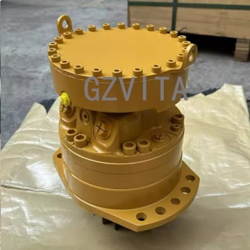
Hangood Slew Reduction E307E E308 Swing Gearbox...
2025-12-10
Brand Name
Hangood
Place of Origin
Guangzhou, China
Warranty
3 Months
Video outgoing-inspection
Provided
Machinery Test Report
Not Available
Part name
Swing Gearbox
Model
E307E E308
Part number
589-5725 5895725
Delivery
Air/Express/Sea etc.
MOQ
1 Piece
10
view
detail
573-8753Swing Device: Rotation Gearbox for Swin...
2025-12-10
Closed-loop swing (in some systems)
Dedicated pump and motor circuit for precise control.
Open-loop swing
Uses a section of the main hydraulic circuit with a control valve.
Swing acceleration
Requires extra torque to overcome inertia, provided by initial pressure surge.
Swing deceleration
Controlled by metering outgoing oil flow through the control valve.
Leakage paths
Internal clearances allow minimal oil flow for lubrication and cooling.
Flushing flow
Continuous case drain flow carries away heat and wear particles.
Pressure holding function
Maintains pressure on the low side to prevent motor cavitation.
Load sensing capability
In advanced systems, signals pump to provide only needed pressure.
Swing circuit filtration
Protects the precision motor components from contamination.
Fail-safe operation
Parking brake engages automatically if hydraulic pressure is lost.
Manual release (optional)
Provision to mechanically release the parking brake for towing.
Mounting flange
Secures the motor to the swing gearbox or frame.
Alignment critical
Precise alignment with the pinion gear is essential for longevity.
Heat generation
Inefficiencies and braking action create heat managed by the hydraulic system.
Commissioning procedure
Requires proper case drain line setup and brake bleeding.
Diagnostic ports
Test ports for checking main pressure, case pressure, and brake pressure.
Integration with machine ECM
Modern systems use electronic signals for control and monitoring, working with the machine's Electronic Control Module for optimal performance
11
view
detail
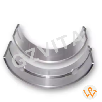
16292-23483 17311-23480 1A091-23480 1J700-23470...
2025-12-09
The primary function of the crankshaft bearing shell, commonly known as the engine bearing, is to provide a precise, low-friction, and durable interface between the high-speed rotating crankshaft journals and the stationary engine block (main bearings) or the connecting rods (rod bearings).
Installed within the bearing saddles, these semi-circular shells are critical for supporting the crankshaft under extreme loads generated by combustion and inertia. Their core purposes are:
Friction Reduction & Lubrication: They are coated with specialized, soft overlay materials (like babbit metal) that minimize friction and wear against the harder crankshaft journal. A thin film of pressurized engine oil, supplied through passages in the block/rod, is maintained between the bearing surface and the journal, creating a hydrodynamic layer for near-frictionless rotation. This prevents direct metal-to-metal contact, known as "bearing seizure."
Load Support & Durability: They absorb and distribute the massive, pulsating forces from piston combustion and connecting rod motion. The strong steel backing of the bearing provides structural integrity to withstand these loads, prevent crankshaft deflection, and contribute to the engine's overall rigidity.
Heat Dissipation & Debris Management: The bearings aid in transferring heat away from the crankshaft journals into the surrounding engine block, which is cooled by coolant. Their soft surface layer can also temporarily embed tiny abrasive particles from engine wear, preventing them from scoring the critical crankshaft surface—a property known as "conformability."
Alignment & Precision: They ensure precise crankshaft positioning and alignment within the engine block, which is essential for maintaining correct piston travel, valve timing, and overall engine balance.
In summary, these unassuming components are vital for converting reciprocating piston motion into smooth rotary power with minimal energy loss, while ensuring the longevity and reliable operation of the engine's core rotating assembly.
13
view
detail
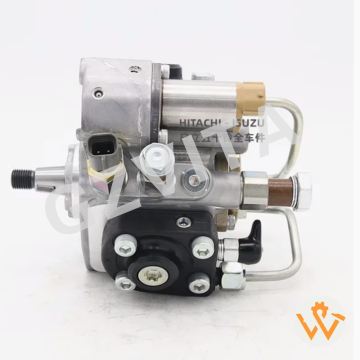
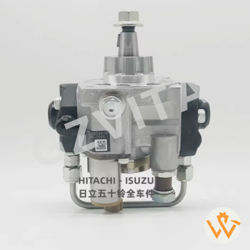
Kingcat 8-98091565-1 294050-0105 Fuel Injection...
2025-12-09
1.
Torque control - Shapes the fuel delivery curve to optimize engine torque across the RPM range.
2.
3.
Shut-off solenoid - An electrically operated valve to cut fuel and stop the engine.
4.
5.
Pressure relief valve - Protects the system from excessive pressure.
6.
7.
Fuel return system - Returns excess and leakage fuel back to the tank.
8.
9.
Leak-off lines - Carry fuel that leaks past plungers and injector needles back to the tank.
10.
11.
Cavitation prevention - Proper system design and feed pressure to prevent fuel vapor bubbles.
12.
13.
Pressure wave propagation - The speed of sound in fuel affects injection timing in line systems.
14.
15.
Dosing - The precise measurement of a small, fixed volume of fuel per stroke.
16.
17.
Delivery stroke - The active portion of the plunger's travel that pressurizes fuel.
18.
19.
Pre-stroke (in some pumps) - An initial plunger movement that can affect timing.
20.
21.
Rack position sensor - Sends a signal to the ECU indicating fuel delivery level.
22.
23.
Needle lift sensor - In some systems, provides feedback on exact injection start.
24.
25.
Rail pressure sensor - Critical for ECU control in Common Rail systems.
26.
27.
Cam profile - The shape of the cam lobe determines plunger velocity and pressure rise rate.
28.
29.
Self-bleeding - Many pumps are designed to purge air automatically from the system.
30.
31.
Synchronized operation - The pump's cycle is precisely timed to the engine's crankshaft position for accurate cylinder fueling.
14
view
detail
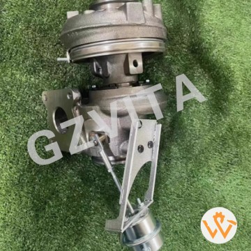
Turbocharger 904273-5002 603-2705 593-1527 528-...
2025-12-09
Clean lubrication vents - Ensure they are not blocked.
Monitor filter pressure drop - High differential means clogging.
Check gearbox oil - For geared models, level and condition.
Inspect anti-vibration mounts - Replace if worn or cracked.
Test alarm/shutdown sensors - Verify they trigger correctly.
Clean cooling fins/fans - Ensure efficient heat dissipation.
Verify rotation direction - Ensure it matches design direction.
Check for unusual odors - Burning smells can indicate problems.
Inspect instrumentation gauges - Ensure they are accurate/functional.
Test manual overrides - Ensure they operate if needed.
Verify oil grade - Use only manufacturer-recommended oil.
Check for loose wiring - Secure all electrical connections.
Inspect for oil leaks at gaskets - Tighten or replace as necessary.
Review maintenance log - Confirm all tasks are up-to-date.
15
view
detail
Genuine 8-97306044-9 8-97306044-8 Fuel Injectio...
2025-12-09
Mechanical fuel injection pump - Traditional system used in many Isuzu engines.
High-pressure generation - Creates pressure far exceeding the engine's compression pressure.
In-line pump design - Features a separate plunger and barrel for each cylinder, aligned in a row.
Distributor-type pump (VE) - A single pumping element distributes fuel to each injector in firing order.
Common Rail system (modern) - Uses a high-pressure rail to supply fuel to electronically controlled injectors.
Plunger and barrel assembly - The core pumping element where reciprocating motion creates pressure.
Camshaft-driven - Pump is driven by and synchronized with the engine camshaft.
Reciprocating plunger - Moves up and down within its barrel to pressurize fuel.
Helical control groove - On the plunger, regulates fuel delivery by varying the spill port uncover timing.
Fuel metering - Precisely controls the volume of fuel delivered per stroke.
Delivery valve - A one-way valve that ensures sharp injection cutoff and prevents drip.
Port-and-helix metering - The plunger's rotation changes the effective stroke via the helical groove alignment with the spill port.
Governor linkage - Connects to the accelerator and controls the pump's rack or control sleeve.
Centrifugal governor - Uses rotating weights to automatically control maximum and idle speeds.
Control rack (in-line pumps) - A toothed rod that rotates all plungers simultaneously to change fuel delivery.
Control sleeve (distributor pumps) - Slides to alter the effective stroke of the single plunger.
Timing advance mechanism - Automatically advances injection timing as engine speed increases.
Hydraulic timing advance - Uses fuel pressure to move the pump's internal cam ring.
Feed pump - A low-pressure transfer pump that supplies fuel from the tank to the injection pump.
Vane-type supply pump - Common in distributor pumps to provide internal fuel feed and lubrication.
Fuel pressure regulation - Maintains correct internal feed pressure for proper operation.
Full-load stop - A mechanical adjustment limiting maximum fuel delivery to prevent over-fueling.
Idle speed adjustment - Sets the minimum stable running speed.
Internal fuel lubrication - Fuel itself lubricates the pump's internal moving parts.
Fuel cooling - Circulating fuel helps carry away heat from the pump.
Spill port - The opening in the barrel that, when uncovered by the plunger's groove, ends delivery.
Beginning of delivery - The moment the plunger closes the inlet port, pressure starts to rise.
End of delivery - The moment the plunger's helical groove aligns with the spill port, pressure collapses.
Constant-pressure chamber (common rail) - The "rail" that stores fuel at ultra-high pressure (e.g., 1600-2500 bar).
High-pressure fuel lines - Robust tubing connecting the pump to the injectors or rail.
Pressure accumulation - Common Rail stores pressurized fuel, ready for instant injection.
Electronic control - An Electronic Control Unit (ECU) precisely governs injection timing and duration in modern systems.
Solenoid-operated injectors - The ECU energizes a solenoid to open the injector nozzle.
Piezoelectric injectors - Use a crystal stack for faster, more precise multiple injections.
16
view
detail
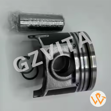
High quality piston bushing for Kubota V2607 pi...
2025-12-09
1.
High-strength aluminum alloy - Primary material for most pistons.
2.
Precision cast aluminum - Common method for producing complex piston shapes.
3.
Forged aluminum - Used in high-performance or heavy-duty models for superior strength.
4.
Excellent thermal conductivity - Aluminum efficiently transfers heat from the crown.
5.
Low density - Keeps reciprocating mass low, improving engine responsiveness.
6.
Good wear resistance - With appropriate surface treatments and ring coatings.
7.
High silicon aluminum alloy - Silicon particles enhance strength and reduce thermal expansion.
8.
Hypereutectic alloy - Contains over 12% silicon for durability and low expansion.
9.
Eutectic alloy - Contains around 12% silicon, a common balance of properties.
10.
Precision-machined - To exact tolerances for optimal fit and performance.
11.
Anodized surface treatment - On some models, for increased surface hardness.
12.
Hard anodizing - Creates a ceramic-like layer on the piston crown or skirt.
13.
Nickel-ceramic coated crown - For thermal barrier and wear protection.
14.
Molybdenum-coated skirt - Reduces friction during the break-in period.
15.
Graphite-coated skirt - Acts as a solid lubricant for smooth initial operation.
16.
Phosphate coating - Helps retain oil and improves break-in.
17.
Tin-plated skirt - Another friction-reducing treatment for run-in.
18.
Forged under high pressure - Aligns the metal grain structure for strength.
19.
Heat-treated (T6 condition) - Solution heat treated and artificially aged for peak strength.
20.
Solution heat treatment - Enhances the alloy's mechanical properties.
21.
Artificial aging - Stabilizes the material after heat treatment.
22.
Precision grinding - For critical surfaces like the ring grooves and pin bore.
23.
Machined ring grooves - To exact specifications for proper ring seating.
24.
Hard anodized ring grooves - In some designs, to prevent groove wear and microwelding.
25.
Cast iron top ring insert - In some heavy-duty pistons, to reinforce the top ring groove.
26.
Ni-Resist insert - A nickel-iron alloy insert for extreme durability in the top ring land.
27.
Cooling gallery design - Internal oil passages for crown cooling, enabled by specific casting techniques.
28.
Asymmetric skirt design - Compensates for thermal expansion and thrust forces.
29.
Cam-ground profile - The skirt is slightly oval when cold, becoming round at operating temperature.
30.
Controlled thermal expansion - Alloy composition is designed to match cylinder bore expansion rates.
31.
High fatigue strength - Resists cracking under repeated combustion pressures.
32.
Good machinability - Allows for precise and efficient manufacturing.
33.
Homogeneous microstructure - Ensures consistent properties throughout the piston.
34.
Low coefficient of thermal expansion - Critical for maintaining proper clearances.
35.
Lightweight - Essential for high-speed engine efficiency and low vibration.