 +86 18578756148


0102030405
Products
01
view
detail
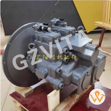
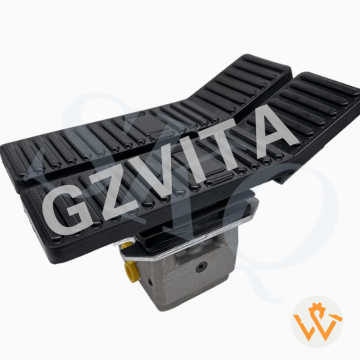
XCMG Excavator XE80 85 90 95 105 115 Traveling ...
2025-12-12
Hydraulic travel motors – Provide rotary power to the track wheels.
Dual independent motors – Allow for counter-rotation and pivot turns.
Travel control levers/pedals – Operator inputs for speed and direction.
Main hydraulic pump – Supplies high-pressure oil to the travel system.
Travel control valves – Direct flow from the pump to the left or right motor.
Two-speed travel selection – Switches between high-speed and high-torque modes.
Speed change valve – Alters motor displacement for speed shifting.
Travel reduction gearbox (final drive) – Reduces motor speed and increases torque.
Sprocket drive – Final drive output shaft directly turns the track sprocket.
Planetary gear sets – Inside the reduction gearbox for compact torque multiplication.
Swing bearings – Support the upper structure and allow it to rotate during travel turns.
Track frame – Rigid structure housing the final drive and rollers.
Hydraulic pressure release – Allows the machine to be towed by disengaging the motors.
Travel brakes – Typically spring-applied, hydraulic-release parking brakes.
Hydraulic counterbalance valves – Prevent uncontrolled movement on slopes.
Pilot pressure system – Provides low-pressure control signals to the main valves.
Neutral bypass – Routes pump flow back to tank when travel levers are not activated.
Load sensing system – Adjusts pump flow and pressure based on demand.
Track tension adjustment – Maintains proper tension via grease cylinders.
Track rollers and idlers – Support and guide the track chain.
Pivot turn (spot turn) – Achieved by driving one track forward and the other reverse.
Gradual turn – Accomplished by varying speed between the two tracks.
Straight-line travel – Both motors receive equal flow and pressure.
Auto-deceleration system – Redects engine speed when travel levers are neutral.
Travel alarm – Sounds when the machine is set to move.
Speed sensors (if equipped) – Monitor track speed for control or monitoring systems.
Travel pressure relief valves – Protect the system from overloads.
Case drain lines – Return internal leakage oil from motors back to the tank.
Hydrostatic transmission principle – Uses variable hydraulic flow for infinite speed control.
Integrated pump-motor circuit – Forms a closed-loop for efficient power transfer.
02
view
detail
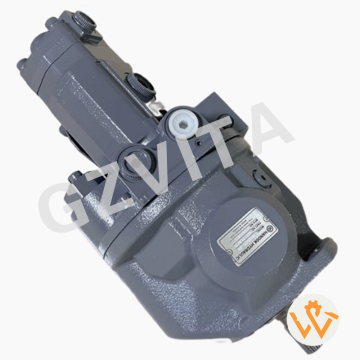
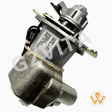
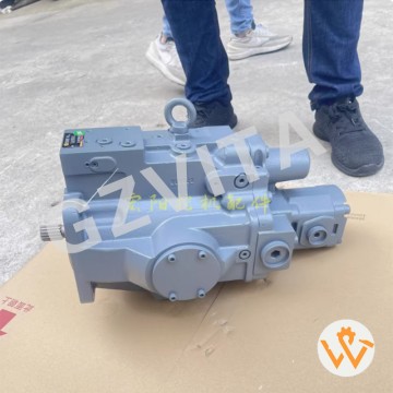
SY16 SY26 SY35 E301.6 Hydraulic Pump CASAPPA MV...
2025-12-12
Use only recommended hydraulic oil with proper viscosity and cleanliness.
Maintain oil temperature within the specified operating range (e.g., 30-70°C).
Ensure effective filtration to prevent contamination from entering the system.
Prime the pump properly before initial start-up to avoid dry running.
Avoid prolonged operation at maximum pressure settings to reduce wear.
Monitor for abnormal noises (cavitation, knocking) during operation.
Check for external leaks regularly at seals, connections, and casing.
Verify proper drive alignment to prevent bearing and shaft damage.
Allow a gradual warm-up period in cold environments before full load.
Maintain correct reservoir oil level to prevent pump cavitation.
Bleed air from the system thoroughly after maintenance or oil changes.
Follow correct start/stop procedures to minimize pressure spikes.
Avoid sudden directional or load changes where possible.
Inspect mounting bolts periodically to ensure they are tight and secure.
Protect the pump from extreme vibration through proper installation.
Use a pressure gauge to monitor system performance against specifications.
Do not exceed the maximum rated speed (RPM) for the pump.
Ensure the pump case drain line is unobstructed and routed correctly.
Implement a regular oil analysis program to monitor fluid condition.
Shut down immediately if a sudden loss of pressure or flow occurs.
Keep the pump and surrounding area clean from dirt and debris.
Operate within the pump's specified displacement and pressure envelope.
Ensure all control linkages (if equipped) move freely without binding.
Avoid moisture ingress into the hydraulic system.
Use recommended flushing procedures when changing oil types.
Follow proper storage procedures if the pump is to be out of service.
Label all hydraulic lines during disassembly for correct reassembly.
Apply thread sealant correctly on fittings to prevent leaks and contamination.
Train operators on basic pump function and alarm indicators.
Adhere strictly to the manufacturer's (Hengli) maintenance schedule and instructions.
03
view
detail
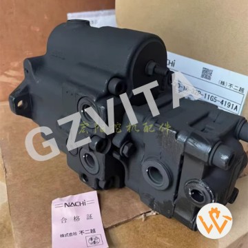
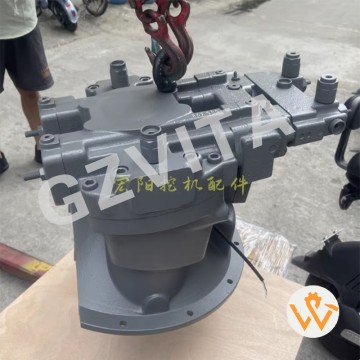
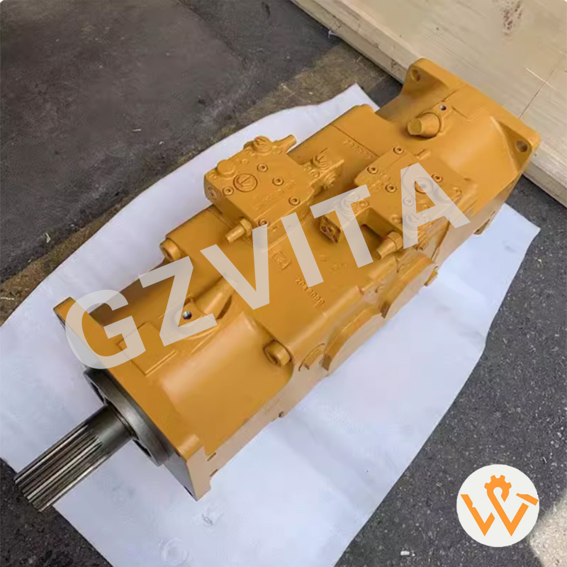
AP2D36 Hydraulic Main Pump ZX70-5A ZX70-5G 70-6...
2025-12-12
Daily visual inspection – Check for external leaks, cracks, or damage.
Monitor hydraulic oil level – Ensure it is within the recommended range before operation.
Check oil temperature – Avoid operation beyond the specified temperature limit.
Listen for abnormal noises – Unusual sounds may indicate cavitation or internal wear.
Inspect pump mounting bolts – Ensure they are tight and secure.
Verify drive coupling condition – Look for wear, cracks, or misalignment.
Check suction lines and filters – Prevent restrictions or air ingress.
Monitor system pressure – Use gauges to detect abnormal fluctuations.
Inspect case drain line – Ensure it is unobstructed and not leaking excessively.
Maintain oil cleanliness – Change filters regularly and use clean oil.
Avoid dry running – Always prime the pump before starting.
Warm up the system – Operate at low pressure and flow in cold conditions.
Prevent contamination – Keep the reservoir and fill area clean.
Check for overheating – Monitor pump housing temperature during operation.
Avoid prolonged operation at maximum pressure – Reduce stress on the pump.
Inspect hoses and fittings – Look for wear, leaks, or loose connections.
Verify proper belt tension – For belt-driven pumps, ensure correct tension.
Monitor oil condition – Look for discoloration, foam, or contamination.
Check for air in the system – Bleed air if foaming or erratic operation occurs.
Ensure adequate ventilation – Prevent heat buildup around the pump.
Follow manufacturer’s operating limits – Adhere to pressure and flow specifications.
Use recommended hydraulic oil – Follow viscosity and grade requirements.
Avoid sudden pressure spikes – Operate controls smoothly to prevent shocks.
Inspect electrical connections – For electric-driven pumps, ensure secure wiring.
Record operating hours – Schedule maintenance based on service intervals.
Check alignment – Ensure the pump is properly aligned with the drive source.
Monitor pump vibration – Excessive vibration may indicate imbalance or wear.
Test relief valve function – Verify proper pressure relief during operation.
Keep maintenance records – Document inspections, repairs, and part replacements.
Train operators – Ensure they understand proper pump operation and early warning signs of failure.
04
view
detail
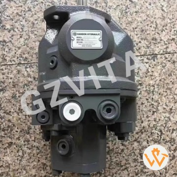
ZAX450 ZAX470 490-5A Hydraulic Main Pump K5V200...
2025-12-12
Daily visual inspection – Check for external leaks, cracks, or damage.
Monitor hydraulic oil level – Ensure it is within the recommended range before operation.
Check oil temperature – Avoid operation beyond the specified temperature limit.
Listen for abnormal noises – Unusual sounds may indicate cavitation or internal wear.
Inspect pump mounting bolts – Ensure they are tight and secure.
Verify drive coupling condition – Look for wear, cracks, or misalignment.
Check suction lines and filters – Prevent restrictions or air ingress.
Monitor system pressure – Use gauges to detect abnormal fluctuations.
Inspect case drain line – Ensure it is unobstructed and not leaking excessively.
Maintain oil cleanliness – Change filters regularly and use clean oil.
Avoid dry running – Always prime the pump before starting.
Warm up the system – Operate at low pressure and flow in cold conditions.
Prevent contamination – Keep the reservoir and fill area clean.
Check for overheating – Monitor pump housing temperature during operation.
Avoid prolonged operation at maximum pressure – Reduce stress on the pump.
Inspect hoses and fittings – Look for wear, leaks, or loose connections.
Verify proper belt tension – For belt-driven pumps, ensure correct tension.
Monitor oil condition – Look for discoloration, foam, or contamination.
Check for air in the system – Bleed air if foaming or erratic operation occurs.
Ensure adequate ventilation – Prevent heat buildup around the pump.
Follow manufacturer’s operating limits – Adhere to pressure and flow specifications.
Use recommended hydraulic oil – Follow viscosity and grade requirements.
Avoid sudden pressure spikes – Operate controls smoothly to prevent shocks.
Inspect electrical connections – For electric-driven pumps, ensure secure wiring.
Record operating hours – Schedule maintenance based on service intervals.
Check alignment – Ensure the pump is properly aligned with the drive source.
Monitor pump vibration – Excessive vibration may indicate imbalance or wear.
Test relief valve function – Verify proper pressure relief during operation.
Keep maintenance records – Document inspections, repairs, and part replacements.
Train operators – Ensure they understand proper pump operation and early warning signs of failure.
05
view
detail
Original Excavator Parts ZAX60 ZAX65 Main Pump ...
2025-12-12
Daily visual inspection – Check for external leaks, cracks, or damage.
Monitor hydraulic oil level – Ensure it is within the recommended range before operation.
Check oil temperature – Avoid operation beyond the specified temperature limit.
Listen for abnormal noises – Unusual sounds may indicate cavitation or internal wear.
Inspect pump mounting bolts – Ensure they are tight and secure.
Verify drive coupling condition – Look for wear, cracks, or misalignment.
Check suction lines and filters – Prevent restrictions or air ingress.
Monitor system pressure – Use gauges to detect abnormal fluctuations.
Inspect case drain line – Ensure it is unobstructed and not leaking excessively.
Maintain oil cleanliness – Change filters regularly and use clean oil.
Avoid dry running – Always prime the pump before starting.
Warm up the system – Operate at low pressure and flow in cold conditions.
Prevent contamination – Keep the reservoir and fill area clean.
Check for overheating – Monitor pump housing temperature during operation.
Avoid prolonged operation at maximum pressure – Reduce stress on the pump.
Inspect hoses and fittings – Look for wear, leaks, or loose connections.
Verify proper belt tension – For belt-driven pumps, ensure correct tension.
Monitor oil condition – Look for discoloration, foam, or contamination.
Check for air in the system – Bleed air if foaming or erratic operation occurs.
Ensure adequate ventilation – Prevent heat buildup around the pump.
Follow manufacturer’s operating limits – Adhere to pressure and flow specifications.
Use recommended hydraulic oil – Follow viscosity and grade requirements.
Avoid sudden pressure spikes – Operate controls smoothly to prevent shocks.
Inspect electrical connections – For electric-driven pumps, ensure secure wiring.
Record operating hours – Schedule maintenance based on service intervals.
Check alignment – Ensure the pump is properly aligned with the drive source.
Monitor pump vibration – Excessive vibration may indicate imbalance or wear.
Test relief valve function – Verify proper pressure relief during operation.
Keep maintenance records – Document inspections, repairs, and part replacements.
Train operators – Ensure they understand proper pump operation and early warning signs of failure.
06
view
detail
Zx30U Main Pump Zx27 Hydraulic Pump Nachi PVD-1...
2025-12-12
Daily visual inspection – Check for external leaks, cracks, or damage.
Monitor hydraulic oil level – Ensure it is within the recommended range before operation.
Check oil temperature – Avoid operation beyond the specified temperature limit.
Listen for abnormal noises – Unusual sounds may indicate cavitation or internal wear.
Inspect pump mounting bolts – Ensure they are tight and secure.
Verify drive coupling condition – Look for wear, cracks, or misalignment.
Check suction lines and filters – Prevent restrictions or air ingress.
Monitor system pressure – Use gauges to detect abnormal fluctuations.
Inspect case drain line – Ensure it is unobstructed and not leaking excessively.
Maintain oil cleanliness – Change filters regularly and use clean oil.
Avoid dry running – Always prime the pump before starting.
Warm up the system – Operate at low pressure and flow in cold conditions.
Prevent contamination – Keep the reservoir and fill area clean.
Check for overheating – Monitor pump housing temperature during operation.
Avoid prolonged operation at maximum pressure – Reduce stress on the pump.
Inspect hoses and fittings – Look for wear, leaks, or loose connections.
Verify proper belt tension – For belt-driven pumps, ensure correct tension.
Monitor oil condition – Look for discoloration, foam, or contamination.
Check for air in the system – Bleed air if foaming or erratic operation occurs.
Ensure adequate ventilation – Prevent heat buildup around the pump.
Follow manufacturer’s operating limits – Adhere to pressure and flow specifications.
Use recommended hydraulic oil – Follow viscosity and grade requirements.
Avoid sudden pressure spikes – Operate controls smoothly to prevent shocks.
Inspect electrical connections – For electric-driven pumps, ensure secure wiring.
Record operating hours – Schedule maintenance based on service intervals.
Check alignment – Ensure the pump is properly aligned with the drive source.
Monitor pump vibration – Excessive vibration may indicate imbalance or wear.
Test relief valve function – Verify proper pressure relief during operation.
Keep maintenance records – Document inspections, repairs, and part replacements.
Train operators – Ensure they understand proper pump operation and early warning signs of failure.
07
view
detail
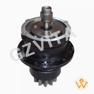
M318 M318C M318D M320 M322C M322D Swing Gearbox...
2025-12-12
Closed-loop swing (in some systems)
Dedicated pump and motor circuit for precise control.
Open-loop swing
Uses a section of the main hydraulic circuit with a control valve.
Swing acceleration
Requires extra torque to overcome inertia, provided by initial pressure surge.
Swing deceleration
Controlled by metering outgoing oil flow through the control valve.
Leakage paths
Internal clearances allow minimal oil flow for lubrication and cooling.
Flushing flow
Continuous case drain flow carries away heat and wear particles.
Pressure holding function
Maintains pressure on the low side to prevent motor cavitation.
Load sensing capability
In advanced systems, signals pump to provide only needed pressure.
Swing circuit filtration
Protects the precision motor components from contamination.
Fail-safe operation
Parking brake engages automatically if hydraulic pressure is lost.
Manual release (optional)
Provision to mechanically release the parking brake for towing.
Mounting flange
Secures the motor to the swing gearbox or frame.
Alignment critical
Precise alignment with the pinion gear is essential for longevity.
Heat generation
Inefficiencies and braking action create heat managed by the hydraulic system.
Commissioning procedure
Requires proper case drain line setup and brake bleeding.
Diagnostic ports
Test ports for checking main pressure, case pressure, and brake pressure.
Integration with machine ECM
Modern systems use electronic signals for control and monitoring, working with the machine's Electronic Control Module for optimal performance
08
view
detail
SY55 SY65 SY75 YC60 Pilot Valve Assembly Foot V...
2025-12-12
Dual-function pedal valve
Travel speed control
Swing brake release
Hydraulic pilot pressure control
Proportional flow regulation
Left travel pedal function
Right travel pedal function
Independent track control
Gradual acceleration/deceleration
Neutral position return spring
Anti-slip pedal surface
Wear-resistant pivot mechanism
Environmental seal protection
Over-center detent mechanism
Pilot pressure feedback
Double-sealing design
Ergonomic pedal angle
Corrosion-resistant coating
Quick response characteristic
Low operation effort design
Vibration damping feature
Temperature resistant seals
Plug-in connector design
Integrated mounting bracket
Field serviceable construction
Compatibility with main control valve
Emergency stop capability
Position sensing technology
Machine control integration
Reliability under harsh conditions
09
view
detail
E216B Excavator Machinery Parts 299-9119 Hydrau...
2025-12-12
|
Product Name |
Part Number |
Compatible Models |
|
polit valve |
702-16-03530 |
BP500-7 PC550LC-8 PC38UU-3 PC35MR-2 |
|
Lever |
20Y-43-22211 |
BP500-7 PC200-7 CD110R-2 PC300-8 |
|
knob |
20Y-43-22381 |
PC400LC-6 PC200-6 PB500-7 |
|
boot |
20Y-43-22261 |
BP500-7 PC200-7 CD110R-2 PC300-8 |
|
Plate |
20Y-43-22250 |
BP500-7 PC200-7 CD110R-2 PC300-8 |
10
view
detail
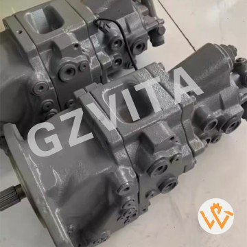
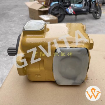
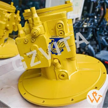
Rexroth A8V080 A8VO80 2054831 Main Pumps Excava...
2025-12-12
Fixed displacement axial piston design
Dual hydraulic pump configuration
Heavy-duty industrial construction
Precision ground cam surface
Hardened alloy steel cylinders
Chromium-plated piston surfaces
Pressure-balanced valve plate
Tapered roller bearing support
High-pressure operation capability
Constant flow output characteristic
Robust cast iron housing
Sintered bronze bushing design
Mechanical drive shaft connection
Port and flange mounting options
ISO standard mounting dimensions
Pressure-balanced piston design
Low noise operation characteristic
Efficient volumetric performance
Reliable sealing system
Minimal internal leakage design
Wide viscosity range compatibility
Corrosion-resistant surface treatment
Precision machined components
Balanced rotating group assembly
Shock load resistant construction
Temperature-stable performance
Easy maintenance accessibility
Interchangeable cartridge design
Factory pre-tested and calibrated
Proven reliability in mobile equipment
11
view
detail
EX30 35U Excavator Hydraulic Pump Assembly AP2D...
2025-12-12
Fixed displacement axial piston design
Dual hydraulic pump configuration
Heavy-duty industrial construction
Precision ground cam surface
Hardened alloy steel cylinders
Chromium-plated piston surfaces
Pressure-balanced valve plate
Tapered roller bearing support
High-pressure operation capability
Constant flow output characteristic
Robust cast iron housing
Sintered bronze bushing design
Mechanical drive shaft connection
Port and flange mounting options
ISO standard mounting dimensions
Pressure-balanced piston design
Low noise operation characteristic
Efficient volumetric performance
Reliable sealing system
Minimal internal leakage design
Wide viscosity range compatibility
Corrosion-resistant surface treatment
Precision machined components
Balanced rotating group assembly
Shock load resistant construction
Temperature-stable performance
Easy maintenance accessibility
Interchangeable cartridge design
Factory pre-tested and calibrated
Proven reliability in mobile equipment
12
view
detail
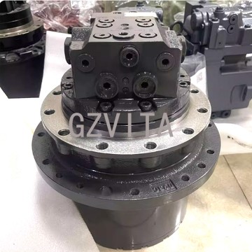
FR480E Fan Motor KP30.31S0-A8K9 Hydraulic Motor...
2025-12-12
Motor type - Axial piston hydraulic motor
Rotation speed - Rated RPM under specified flow
Displacement - Volume per revolution (e.g., cc/rev)
Maximum pressure - Continuous and peak operating pressure
Torque output - Rated and maximum torque (N·m)
Flow requirements - Recommended flow range (L/min)
Rotation direction - Bidirectional (clockwise/counterclockwise)
Shaft type - Splined or keyed output shaft
Shaft dimensions - Diameter and spline specifications
Mounting flange - Standardized flange pattern
Port configuration - SAE or metric threaded ports
Port size - Inlet/outlet port dimensions
Case drain port - Required for internal leakage return
Filtration requirement - Minimum oil cleanliness level
Oil viscosity range - Recommended operating viscosity
Maximum temperature - Allowable oil temperature limit
Brake type - Spring-applied hydraulic release parking brake
Brake torque - Holding torque capacity
Brake release pressure - Required pressure to disengage brake
Reduction ratio - Gearbox reduction ratio (if integrated)
Gear type - Planetary or spur gear design
Bearing type - Tapered roller or ball bearings
Weight - Total assembly weight
Dimensions - Overall length, width, and height
Material specification - Housing and gear materials
Shaft seal type - High-pressure rotary seal
Efficiency rating - Volumetric and mechanical efficiency
Starting torque - Breakaway torque characteristics
Backlash specification - Gear train backlash tolerance
Lubrication method - Splash or forced lubrication
Cooling requirement - Recommended case drain flow
Noise level - Typical operating decibel range
Service life - Expected lifespan under normal conditions
Maintenance interval - Recommended inspection periods
Pressure setting - Relief valve cracking pressure
Leakage rate - Acceptable internal leakage specification
Shock load capacity - Maximum allowable momentary overload
Mounting orientation - Allowable installation positions
Rotation angle limit - Unlimited continuous rotation
Acceleration time - Time to reach full speed
Deceleration time - Stopping time under load
Back pressure limit - Maximum allowable case pressure
Smoothness rating - Rotation stability and consistency
Environmental rating - IP rating for dust/water resistance
Vibration resistance - Tolerance to operational vibration
Alignment requirement - Shaft alignment specifications
Thermal characteristics - Heat generation and dissipation
Pressure drop - Flow resistance through the motor
Response time - Reaction time to control signals
Compatibility - Hydraulic oil type compatibility
Testing standard - Industry testing specifications met
Certification - Quality and safety certifications
Warranty period - Manufacturer warranty duration
Replacement part number - OEM part identification
Cross-reference - Compatible alternative part numbers
Country of origin - Manufacturing location
Packaging specifications - Shipping package details
Installation torque - Bolt tightening specifications
Break-in procedure - Initial operation requirements
Performance curve availability - Torque-speed-pressure characteristic charts
13
view
detail
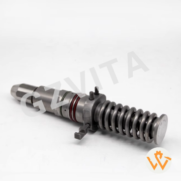
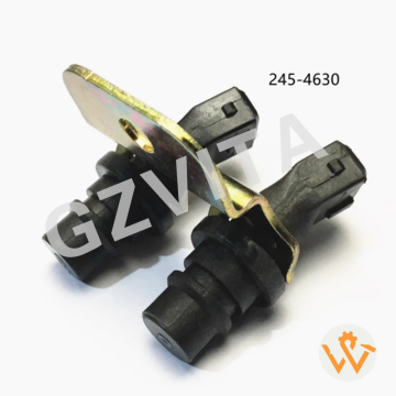
Speed Engine Timing Sensor for Caterpillar CAT ...
2025-12-12
OE NO.
245-4630
Condition
New
Place of Origin
Guangdong, China
Purpose
for replace/repair
Brand Name
WANATOP
Warranty
12 Months
Type
Speedometer Sensor
Model Number
245-4630 236-6221 109-7194 109-7195
Car Make
For Caterpillar CAT C7 C9 3126 3126B 3126E 3116
Universal Fitment
Yes
Size
OEM Size
Interchange No.
245-4630 236-6221 109-7194 109-7195
Payment
Union.Paypal TT
Shipping Term
Request
Warranty
12 Months
Product Name
Car Angle Sensor
Packing
100% Neutral Paper Boxes
Delivery time
3-7 Days
Quality
100%tested
14
view
detail
295-9676 for SALE Power Parts Original Pump E37...
2025-12-12
Variable displacement axial piston pumps (dual).
Load sensing pressure-flow compensated (LSPC) system.
Swashplate angle control for output adjustment.
Hydraulic or electro-hydraulic servo control.
Closed-center load sensing (CLSS) circuit.
Power sharing between pumps.
Pressure cut-off (PCO) function.
Horsepower matching with the engine.
Cross-sensing between pump sections.
Displacement feedback mechanism.
High-pressure rotating groups.
Stationary valve plates.
Integral charge pump for make-up flow.
Case drain and flushing circuit.
Main system relief valves.
Anti-cavitation check valves.
Pressure compensator valves.
Flow compensator valves.
Load signal network (LS lines).
Pilot pressure supply circuit.
Pump controller (electronic or hydraulic).
Proportional solenoid valves (if equipped).
Pressure transducers for control feedback.
Mounting and drive system to the engine.
Breather and case drain ports.
Filtration system for charge and case drain oil.
Temperature management via case drain flow.
Efficiency optimization logic.
Fail-safe pressure and flow limiting.
Integrated diagnostic capability.
15
view
detail
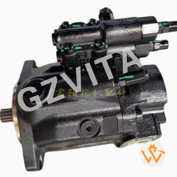
A10VD43 Rexroth Hydraulic Piston Pump A10VD43SR...
2025-12-12
Variable displacement axial piston pumps (dual).
Load sensing pressure-flow compensated (LSPC) system.
Swashplate angle control for output adjustment.
Hydraulic or electro-hydraulic servo control.
Closed-center load sensing (CLSS) circuit.
Power sharing between pumps.
Pressure cut-off (PCO) function.
Horsepower matching with the engine.
Cross-sensing between pump sections.
Displacement feedback mechanism.
High-pressure rotating groups.
Stationary valve plates.
Integral charge pump for make-up flow.
Case drain and flushing circuit.
Main system relief valves.
Anti-cavitation check valves.
Pressure compensator valves.
Flow compensator valves.
Load signal network (LS lines).
Pilot pressure supply circuit.
Pump controller (electronic or hydraulic).
Proportional solenoid valves (if equipped).
Pressure transducers for control feedback.
Mounting and drive system to the engine.
Breather and case drain ports.
Filtration system for charge and case drain oil.
Temperature management via case drain flow.
Efficiency optimization logic.
Fail-safe pressure and flow limiting.
Integrated diagnostic capability.
16
view
detail
M315D M317D A11VO130 Hydraulic Main Pump for Ex...
2025-12-12
Variable displacement axial piston pumps (dual).
Load sensing pressure-flow compensated (LSPC) system.
Swashplate angle control for output adjustment.
Hydraulic or electro-hydraulic servo control.
Closed-center load sensing (CLSS) circuit.
Power sharing between pumps.
Pressure cut-off (PCO) function.
Horsepower matching with the engine.
Cross-sensing between pump sections.
Displacement feedback mechanism.
High-pressure rotating groups.
Stationary valve plates.
Integral charge pump for make-up flow.
Case drain and flushing circuit.
Main system relief valves.
Anti-cavitation check valves.
Pressure compensator valves.
Flow compensator valves.
Load signal network (LS lines).
Pilot pressure supply circuit.
Pump controller (electronic or hydraulic).
Proportional solenoid valves (if equipped).
Pressure transducers for control feedback.
Mounting and drive system to the engine.
Breather and case drain ports.
Filtration system for charge and case drain oil.
Temperature management via case drain flow.
Efficiency optimization logic.
Fail-safe pressure and flow limiting.
Integrated diagnostic capability.