 +86 18578756148


0102030405
Products
01
view
detail
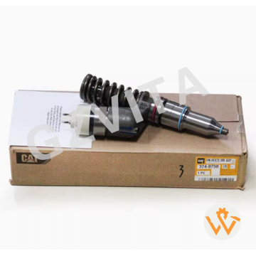
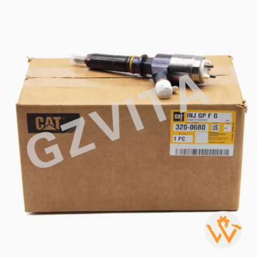
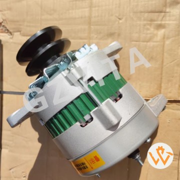
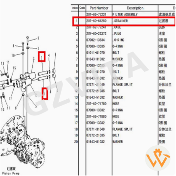
PC450-8 Engine Alternator 600-825-5151 600-825-...
2025-12-11
Daily visual inspection for oil, coolant, or fuel leaks.
Check engine oil level before each startup using the dipstick.
Inspect coolant level in the expansion tank.
Monitor exhaust color for abnormal smoke (black/blue/white).
Listen for unusual noises like knocking or grinding during operation.
Check belt tension and condition (cracks, glazing, wear).
Inspect electrical connections for tightness and corrosion.
Verify battery terminal condition (clean, tight, no corrosion).
Monitor control panel gauges (voltage, frequency, temperature).
Check fuel level and water separator; drain if necessary.
Clean air intake filters or check restriction indicators.
Inspect radiator fins for debris blockage and clean if needed.
Verify proper ventilation around the generator set.
Check for loose or missing fasteners on the unit.
Monitor running hours for scheduled maintenance intervals.
Record operational data (voltage, frequency, load) if possible.
Inspect exhaust system for leaks or damage.
Check mounting bolts and vibration isolators for tightness.
Look for wiring insulation damage or chafing.
Verify proper grounding of the generator frame.
Test emergency stop function periodically (if equipped).
Check for abnormal vibrations during operation.
Inspect cooling fan and shroud for damage.
Monitor oil pressure (if gauge equipped) during operation.
Verify fuel filter condition and replace as scheduled.
Check oil filter for leaks and replace per schedule.
Inspect starter motor and alternator connections.
Ensure drip trays are clean and free of fluid accumulation.
Keep the area around the generator clean and unobstructed.
Follow the manufacturer's (Komatsu) maintenance schedule precisely for oil changes, filter replacements, and major services.
02
view
detail
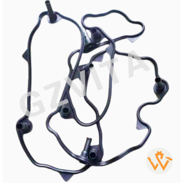
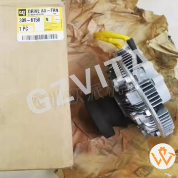
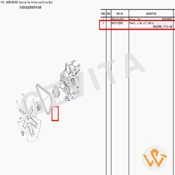
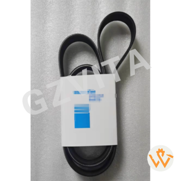
Factory Direct Sale Guaranteed 04121-22264 Fan ...
2025-12-11
Chloroprene rubber (Neoprene)
Polyester cord (fiberglass-reinforced)
Aramid fiber (Kevlar®-type)
High-tenacity nylon fabric
Pre-stretched polyester cords
Carbon black compound
Heat-resistant rubber compound
Oil-resistant synthetic rubber
Antiozonant additives
Antioxidant additives
Sulfur or peroxide curing system
Soft rubber tooth facing
Hard rubber backing
Conductive rubber compound
Hypalon® (CSM) coating
Molded cogs (teeth)
Concave sidewalls
Precision molding process
Steel cord reinforcement
Fiber-loaded rubber compound
Rubber-impregnated fabric
Adhesive system for cord bonding
Precision grinding of teeth
Chamfered tooth edges
Molded timing marks
Low hysteresis rubber
Abrasion-resistant surface
Flex fatigue-resistant compound
Static dissipative construction
Hydrolysis-resistant treatment
03
view
detail
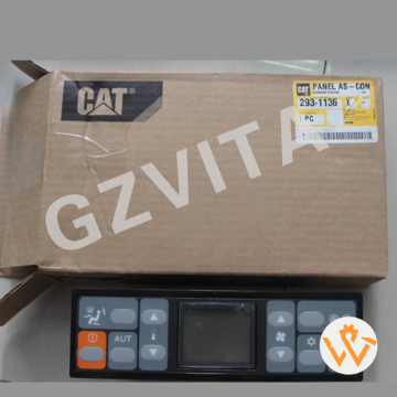
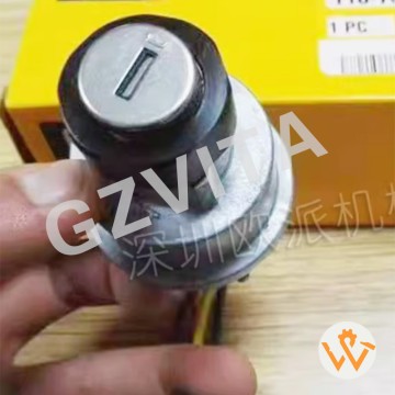
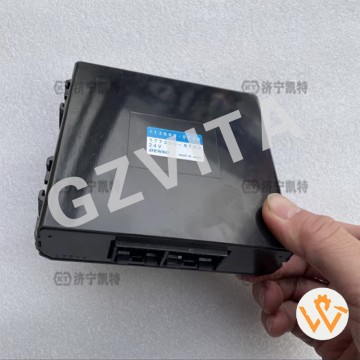
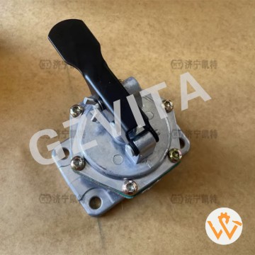
Komatsu Genuine Parts Air Conditioning Control ...
2025-12-11
Operate with clean, dry hands to prevent button/screen damage.
Avoid pressing buttons with sharp objects that may scratch the panel.
Turn off the AC system before shutting down the engine.
Allow the engine to run briefly before activating the AC compressor.
Set the fan to low speed when starting the AC for initial cooling.
Adjust temperature gradually instead of extreme high-low changes.
Use the "Recirculation" mode in dusty or polluted environments.
Switch to "Fresh Air" mode periodically to prevent window fogging.
Clean the panel surface regularly with a soft, dry microfiber cloth.
Avoid using chemical cleaners that may damage the display or buttons.
Check that all buttons respond correctly during daily inspections.
Verify display readability in different lighting conditions.
Keep the panel area free from loose items that could press buttons.
Close windows and doors when using AC for maximum efficiency.
Use the "Auto" mode when possible for optimal system balance.
Monitor for unusual display symbols or error codes.
Listen for abnormal noises when adjusting fan speeds or modes.
Check air output temperature from vents to verify cooling/heating.
Avoid blocking air intake and vents with objects or debris.
Park in shade when possible to reduce initial cooling load.
Turn off the AC compressor several minutes before engine shutdown.
Use the defrost mode to clear windshield fog quickly.
Report unresponsive controls or display issues immediately.
Keep the operator's manual accessible for mode reference.
Avoid spilling liquids on or near the control panel.
Do not cover the panel with maps, cloth, or other materials.
Verify that the cabin air filter is clean for proper airflow.
Use sunshades on windows to reduce cabin heat buildup.
Schedule regular AC system maintenance including panel checks.
Follow the manufacturer's recommended settings for fuel efficiency.
04
view
detail
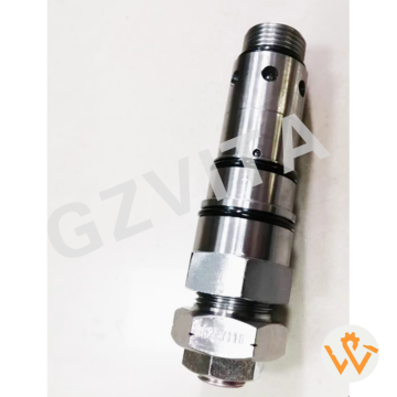
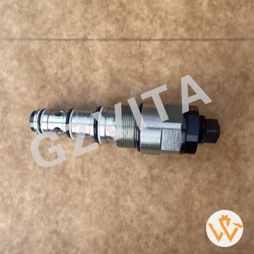
Construction Machinery Parts 723-40-56900 723-4...
2025-12-11
Pressure regulation for individual functions – Sets specific pressure limits for boom, arm, bucket, and swing circuits.
Function-specific overload protection – Prevents damage to cylinders and motors during overload.
Work tool pressure customization – Allows adjustment of force for different attachments.
Circuit priority pressure control – Manages pressure distribution between simultaneous functions.
Shock absorption in implement circuits – Cushions pressure spikes during sudden load changes.
Fine control of cylinder speed and force – By adjusting pressure, controls movement precision.
Swing circuit pressure regulation – Protects swing motor and gear from excessive torque.
Boom lowering/regeneration pressure control – Manages pressure in boom down circuits for smooth control.
Arm crowding/dumping pressure adjustment – Sets optimal pressure for digging and dumping.
Bucket curling/dumping pressure setting – Adjusts force for loading and material release.
Auxiliary circuit pressure regulation – Controls pressure for hydraulic attachments (breaker, grapple).
Pilot pressure supply regulation – Maintains stable pilot pressure for valve operation.
Load check valve pressure setting – Ensures pressure holding when control levers are neutral.
Anti-cavitation valve pressure control – Prevents vacuum formation in cylinders.
Travel circuit interface pressure regulation – Coordinates with main travel pressure valve.
Pressure compensation between parallel circuits – Balances pressure when multiple functions are used.
Lift capacity limitation – Can be set to limit maximum lift pressure for safety.
Attachment protection – Prevents excessive force from damaging mounted tools.
Operator effort adjustment – Affects the "feel" and responsiveness of controls.
System stability enhancement – Reduces pressure fluctuations for smoother operation.
Energy efficiency optimization – Prevents unnecessary high pressure, reducing fuel consumption.
Heat generation reduction – Limits pressure to decrease hydraulic system heat.
Emergency pressure relief for specific functions – Provides dedicated safety release.
Fine-tuning of work modes – Adjusts pressure settings for different work conditions.
Pressure sequencing for combined operations – Coordinates pressure during complex movements.
Motor stall prevention – Limits pressure to prevent travel or swing motor stalling.
Cylinder cushioning adjustment – Controls end-of-stroke cushioning pressure.
Hydraulic hammer pressure regulation – Sets optimal pressure for breaker operation.
Diagnostic reference point – Pressure readings help diagnose circuit-specific issues.
Performance calibration – Key adjustment point for tailoring machine performance to job requirements
05
view
detail
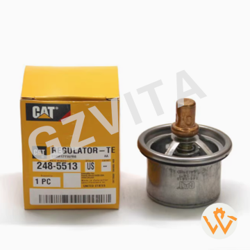
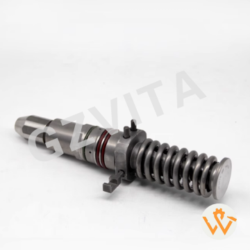
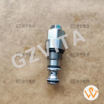
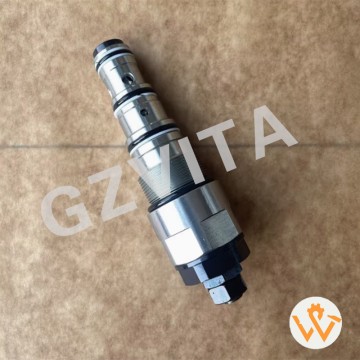
Pressure Relief Valve 702-75-04601 7027504601 f...
2025-12-11
Travel pressure regulation – Sets and controls maximum pressure in the travel circuit.
System pressure protection – Prevents overpressure damage to travel motors and lines.
Torque limitation – Limits maximum torque output to the travel motors.
Shock absorption – Cushions pressure spikes during travel direction changes or impacts.
Smooth acceleration/deceleration – Ensures gradual pressure buildup and release for smooth starts and stops.
Load sensing compensation – Adjusts pressure based on travel resistance (slope, terrain).
Motor protection – Prevents excessive pressure from damaging travel motor components.
Circuit balancing – Helps balance pressure between left and right travel circuits.
Anti-stall function – Reduces pressure to prevent engine stalling under high load.
Pressure override control – Allows temporary pressure increase for high-resistance conditions.
Cross-line relief function – Protects against pressure spikes when one track is locked.
Braking assistance – Controls pressure during hydraulic braking phases.
Directional control stability – Maintains stable pressure during forward/reverse shifts.
Motor displacement control interface – Works with variable displacement travel motors.
Pilot pressure regulation – May regulate pilot pressure for travel control valves.
System efficiency optimization – Adjusts pressure to minimize energy loss.
Speed matching adjustment – Helps synchronize left and right track speeds.
Slope operation safety – Controls pressure to prevent runaway on slopes.
Reduced wear on components – By limiting peak pressures, extends parts life.
Travel priority function – May prioritize flow/pressure to travel over other functions.
Anti-slip control assistance – Works with systems to prevent track slippage.
Hydraulic braking pressure control – Manages pressure during braking.
Pressure maintenance during turns – Adjusts pressure to facilitate smooth turning.
Emergency pressure relief – Provides a safety pressure release in fault conditions.
Fine-tuning of travel effort – Allows adjustment of travel force/power feel.
Integration with main relief valve – Often works in conjunction with the main system relief.
Heat generation reduction – By controlling unnecessary high pressure, reduces heat.
Noise reduction – Smoother pressure control reduces hydraulic noise.
Operator comfort enhancement – Provides predictable and controllable travel response.
Travel performance calibration point – Used to set and fine-tune travel characteristics.
06
view
detail
Excavator Part PC300-7 PC350-8PC400-7 PC450-7 P...
2025-12-11
Multi-layer synthetic fiber media – Primary filtration material for fine particles.
Cellulose-polyester composite – Common blend for balanced performance.
High-efficiency glass microfibers – For high dirt-holding capacity and fine filtration.
Resin-impregnated paper media – Provides stiffness and contaminant retention.
Wire mesh support screen – Internal/external mesh for media structural support.
Perforated steel center tube – Provides internal strength and flow channel.
Galvanized or stainless steel end caps – Corrosion-resistant metal caps.
Polyurethane or nitrile sealing gaskets – For leak-proof housing interface.
Anti-drainback valve silicone – Prevents oil backflow when engine is off.
Bypass valve spring steel – Ensures oil flow if filter is clogged.
Heavy-duty steel outer casing – Protects the filter element.
Powder-coated steel shell – External corrosion protection.
Abrasion-resistant media coating – Withstands high oil velocity.
Heat-resistant adhesives – Bond layers to withstand operating temperatures.
Water-resistant media treatment – Prevents media degradation from water.
Synthetic rubber end seals – Compatible with hydraulic oils and temperatures.
Plastic reinforcement grid – Internal support for pleated media.
Aluminum alloy components – Lightweight structural parts.
Cold-rolled steel spring – For bypass valve operation.
Epoxy sealants – Seal joints against leaks.
Fiberglass reinforcement – In some high-pressure filter designs.
Molded plastic bypass valve body – Lightweight and corrosion-free.
Metal-free media options – For applications requiring low ash content.
Microglass media with synthetic scrim backing – Enhanced durability.
Hydrophobic media treatment – Repels water for improved performance.
Static dissipative materials – Prevent static buildup in the system.
FDA-grade materials – For environmentally sensitive applications.
High-temperature resistant polymers – For gaskets and seals.
Reinforced nylon components – For strength and chemical resistance.
Recyclable material construction – Environmental consideration in design.
07
view
detail
Excavator Parts New Condition PC400-7 PC400-8 P...
2025-12-11
Manual fuel system priming – Removes air from fuel lines after filter changes.
Emergency fuel supply – Provides fuel to the engine if the electric pump fails.
Bleeding air from fuel lines – Purging air after system maintenance or running out of fuel.
Filter priming – Fills new fuel filters to prevent dry starts.
Fuel line pressure testing – Manually pressurizing system to check for leaks.
Pre-start fuel delivery – Ensuring fuel reaches injection pump before cranking.
Cold weather starting aid – Manual priming for easier cold starts.
System venting – Eliminating vapor locks in the fuel system.
Fuel transfer – Moving fuel between tanks or containers.
Drainage assistance – Draining water or contaminated fuel from the system.
Bypassing electric pump – Temporarily replacing electric pump function.
Diagnostic tool – Testing fuel delivery issues manually.
Emergency starting – Priming the system when batteries are weak.
Pressure relief – Releasing pressure before opening fuel system components.
Injection pump lubrication – Providing initial lubrication during assembly.
Sediment removal – Flushing out debris from low points in the fuel lines.
System flushing – Circulating fuel to clean internal passages.
Fuel gauge verification – Checking fuel flow when gauges are suspect.
Priming high-pressure pump – Ensuring the common rail pump is filled.
Leak detection – Building pressure to locate fuel leaks visually.
Manual circulation – Moving fuel through the system without engine operation.
Filter by-pass – Direct fuel flow around clogged filters temporarily.
Fuel sampling – Drawing fuel samples for contamination testing.
Emergency stop reset – Priming after engine shutdown due to fuel starvation.
Water separator draining – Assisting in draining water from fuel/water separators.
Backup to electric lift pump – Secondary fuel supply method.
Training demonstration – Teaching fuel system principles to technicians.
System integrity check – Verifying fuel line and connection tightness.
Prime maintenance tool – Essential for routine fuel system service.
Reliable mechanical backup – Simple, non-electric component for critical fuel delivery.
08
view
detail
PC200-7 Unloading Valve for PC200-7/-8 PC220-7 ...
2025-12-11
Maximum pressure limitation – Prevents system pressure from exceeding safe levels.
Hydraulic system protection – Protects pumps, valves, and cylinders from overpressure damage.
Pressure relief function – Diverts excess pump flow to tank when pressure reaches set point.
Load holding safety – Maintains pressure in cylinders when controls are in neutral.
Thermal management – Relieves pressure to reduce heat generation during stalling.
Shock absorption – Cushions pressure spikes from sudden load changes.
Pump unloading – Allows pump flow to return to tank at low pressure when not needed.
Energy conservation – Reduces power loss and fuel consumption by unloading the pump.
Stall prevention – Prevents engine stalling by relieving pressure at maximum setting.
Cylinder and hose protection – Prevents bursting of hoses and seals.
Stable operation – Maintains consistent system pressure for smooth machine control.
Emergency pressure release – Provides a safe pressure release path in fault conditions.
Boom and arm safety – Holds boom and arm in position without drifting.
Swing brake engagement – Maintains pressure for swing parking brake application.
Travel motor protection – Prevents overpressure in travel circuits.
Implement circuit security – Safeguards attachment hydraulic circuits.
Pilot system pressure regulation – May regulate pressure for pilot control circuits.
Sequence valve function – In some systems, directs flow based on pressure.
System pressure calibration point – Used to set and verify main system pressure.
Noise reduction – Reduces hydraulic noise by preventing excessive pressure.
Cavitation prevention – Maintains sufficient back pressure to avoid vacuum conditions.
Leakage compensation – Compensates for internal leakage in cylinders and valves.
Load sensing system integration – Works with load sensing pumps to control flow.
Multi-function valve operation – May have multiple relief settings for different functions.
Thermal relief capability – Opens at lower pressure if oil temperature is too high.
Anti-shock valve coordination – Works with anti-shock valves to dampen shocks.
Electric override capability – Some models have solenoid-controlled unloading.
Manual override provision – For emergency operation or testing.
Pressure adjustment capability – Can be adjusted to match different working conditions.
System diagnostics indicator – Abnormal pressure readings can indicate other system faults
09
view
detail
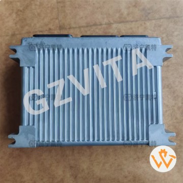
High Quality Controller 7835-26-2003 7835262003...
2025-12-11
CA111 - Pump 1 discharge pressure sensor abnormality (signal out of range).
CA112 - Pump 2 discharge pressure sensor abnormality.
CA122 - Pump 1 control current abnormality (NC/PC solenoid circuit fault).
CA222 - Pump 2 control current abnormality.
CA144 - Pump 1 tilting angle sensor abnormality.
CA244 - Pump 2 tilting angle sensor abnormality.
CA187 - Swing parking brake solenoid abnormality (current fault).
CA342 - Arm regeneration solenoid abnormality.
CA352 - Boom regeneration solenoid abnormality.
CA433 - Travel speed shift solenoid abnormality.
CA525 - Engine control communication error (data from engine ECU lost).
CA551 - CAN bus error (main controller communication fault).
CA552 - Display unit communication error (monitor communication lost).
E01 - Engine overspeed (RPM exceeds maximum limit).
E02 - Engine underspeed (RPM below minimum threshold).
E03 - Engine speed sensor abnormality (signal irregular).
E11 - Common rail pressure sensor abnormality (signal out of range).
E15 - Engine coolant temperature sensor abnormality.
E20 - Intake air temperature sensor abnormality.
E21 - Atmospheric pressure sensor abnormality.
E26 - Coolant level switch abnormality (low coolant warning).
E101 - DPF differential pressure sensor abnormality.
E102 - DPF over-temperature warning.
E103 - DPF regeneration request or failure.
E108 - Exhaust temperature sensor abnormality (DPF inlet/outlet).
E109 - DEF (diesel exhaust fluid) level sensor abnormality (if equipped).
E110 - DEF pressure sensor abnormality (if equipped).
AA10 - Fuel pre-filter warning (water detected or clogging).
HH01 - Hydraulic oil temperature sensor abnormality.
HH02 - Hydraulic oil level switch abnormality (low oil warning).
10
view
detail
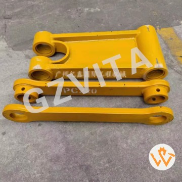
Top Quality Excavator Parts for KomatsuPC100 PC...
2025-12-11
(Linkage)
Fine-grained forged steel
Quenched and tempered steel
High yield strength steel (≥345 MPa)
High tensile strength steel (≥500 MPa)
Impact-resistant steel grade
Abrasion-resistant steel plates
Precision-cut steel profiles
Stress-relieved after welding
Shot-peened surface
Zinc phosphate coating
Powder-coated finish
Ultrasonic tested (UT) material
Certified mill test reports (MTRs)
Weldable high-strength steel
(I-Beam/Center Frame)
Hot-rolled structural steel beams
Box-section fabricated steel
Reinforced flange and web plates
High rigidity steel construction
Full penetration welds at critical joints
Internal rib/stiffener reinforcement
Vibration-damped steel assembly
Primer + epoxy paint system
Galvanized components
Magnetic particle inspected (MPI) welds
Dimensional stability after machining
Fatigue-resistant design steel
Low-temperature impact toughness steel
ISO 630 structural steel compliance
Traceable material batches
11
view
detail
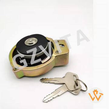
Construction Machinery Parts Excavator Hydrauli...
2025-12-11
1. Precision-engineered pressure relief for optimal cooling system performance.
2. Maintains consistent system pressure to prevent overheating and coolant loss.
3. Durable construction with high-quality materials for long-lasting reliability.
4. Easy to install – a direct OEM replacement for hassle-free maintenance.
5. Ensures proper sealing to avoid coolant leaks and air ingress.
6. Helps extend the lifespan of your Komatsu engine and radiator.
7. Rigorously tested for pressure accuracy and leak-free operation.
8. Corrosion-resistant design suitable for harsh working environments.
9. Keeps coolant at the correct temperature for peak engine efficiency.
10. Prevents vapor lock and boiling overflow in extreme conditions.
11. Affordable yet essential protection for your valuable equipment.
12. A small component with a huge impact on machine uptime and reliability.
13. Trusted by mechanics and operators worldwide for consistent quality.
14. Perfect fit – designed specifically for Komatsu cooling systems.
15. Reduces maintenance costs by preventing cooling system failures.
16. Enhances fuel efficiency by maintaining optimal operating temperature.
17. Heavy-duty spring mechanism for precise pressure control.
18. Built to withstand vibration and shock in tough construction sites.
19. Compatible with standard coolant types and additives.
20. Clear pressure rating markings for easy identification and safety.
21. An essential spare part for every Komatsu owner’s maintenance kit.
22. Protects against radiator damage from pressure spikes.
23. Simple design for reliable performance season after season.
24. Helps avoid costly downtime due to cooling system issues.
25. Engineered to meet or exceed original Komatsu specifications.
26. Ensures safe operation by preventing sudden coolant eruptions.
27. Maintains system integrity in both freezing and scorching climates.
28. A smart investment in preventative care for your machine.
29. Quick-release feature for easy coolant checks and top-ups.
30. Your first line of defense against overheating – choose genuine quality.
12
view
detail
Construction Machinery Parts Engine SAA6D125E-5...
2025-12-11
Visual inspection for cracks - Check for longitudinal cracks on the ribbed side.
Check for fraying or separation - Look for torn edges or separated plies.
Inspect for glazing or shine - A shiny surface indicates slippage and wear.
Look for missing ribs or chunks - Damage to the V-ribs or cog structure.
Examine for oil or grease contamination - Oil degrades rubber and causes slippage.
Check belt tension - Ensure it's within the specified deflection range.
Verify proper alignment - Pulleys must be in line to prevent uneven wear.
Listen for squealing noises - A high-pitched squeal often indicates slippage.
Listen for chirping sounds - Can indicate misalignment or a worn bearing.
Feel for vibration - Excessive vibration during operation suggests wear or imbalance.
Inspect pulley grooves - Worn or damaged grooves can accelerate belt wear.
Check for pulley debris buildup - Clean out any material stuck in the grooves.
Verify belt routing - Ensure it's correctly installed on all pulleys.
Look for signs of overheating - Check for burnt rubber smell or discoloration.
Check belt length - A stretched belt will not maintain proper tension.
Inspect automatic tensioner (if equipped) - Check for smooth operation and proper range.
Check manual tensioner adjustment - Ensure it's locked in the correct position.
Examine belt backside - Look for wear, cracking, or signs of rubbing.
Ensure proper belt type/size - Confirm it matches the machine's specifications.
Check for foreign object damage - Look for cuts or punctures from debris.
Inspect belt during cold start - Listen for noises when the engine is first started.
Monitor belt performance under load - Check for slippage when alternator demand is high.
Look for belt dust - Accumulation of rubber dust indicates excessive wear.
Check mounting bolts - Ensure all pulley and tensioner bolts are tight.
Feel for belt temperature after operation - Excessive heat indicates a problem.
Inspect for coolant or antifreeze contamination - These fluids degrade rubber.
Check the belt's date code - Note installation date for preventive replacement.
Look for inconsistent wear patterns - Can point to a specific pulley issue.
Verify clearance - Ensure the belt doesn't rub against any other components.
Document the inspection findings - Record condition and any corrective actions taken
13
view
detail
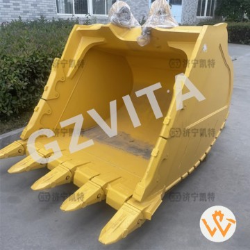
Rock Bucket for Excavators Wear-resistant for 1...
2025-12-11
Engineered to conquer granite, limestone, and basalt with relentless strength.
2. Reinforced design for maximum impact resistance in extreme rock conditions.
3. High-tensil steel construction ensures durability against abrasion and shock loads.
4. Optimized tooth configuration for superior penetration and breakout force.
5. Enhanced side cutters protect against wear and extend bucket lifespan.
6. Ideal for quarry, mining, and heavy-duty excavation applications.
7. Robust structure minimizes deformation under high-stress rock digging.
8. Specialized alloy materials resist cracking and material fatigue.
9. Increased load capacity for efficient rock handling and reduced cycle times.
10. Advanced heat treatment process provides exceptional hardness and toughness.
11. Engineered for optimal weight-to-strength ratio in rugged environments.
12. Compatible with major excavator brands including Caterpillar, Komatsu, and Hitachi.
13. Customizable options for teeth, adapters, and cutting edges available.
14. Reduces maintenance costs with extended service intervals and easy parts replacement.
15. Superior bucket geometry ensures fast filling and efficient material retention.
16. Tested and proven in the world's toughest mining and construction sites.
17. Reinforced backplate and sidewalls for heavy shock absorption.
18. Precision welding techniques ensure structural integrity under extreme forces.
19. Improves productivity with faster digging cycles and reduced equipment wear.
20. Designed to withstand continuous impact and abrasion from blasted rock.
21. Protects your excavator’s front linkage from excessive stress and damage.
22. Heavy-duty rock bucket solutions for 10-ton to 100-ton class excavators.
23. Exclusive wear-resistant lining options for extended service life in abrasive materials.
24. Increases ROI by reducing downtime and bucket replacement frequency.
25. Optimal bucket curvature for aggressive digging and easy material release.
26. Built with reinforced AR400/AR500 steel at critical stress points.
27. Engineered to handle ripped rock, heavy basalt, and other challenging materials.
28. Seamless integration with hydraulic hammer and ripper attachments.
29. Reduces fuel consumption per ton with efficient digging performance.
30. Your ultimate rock-breaking partner – designed to outperform, built to endure.
14
view
detail
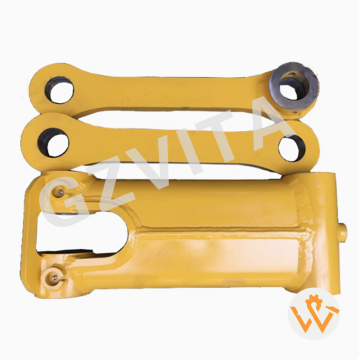
207-70-33120 Excavator Link for PC300-7 PC360-7...
2025-12-11
Daily visual inspection for cracks, deformation, or weld failures on linkage and I-beam.
Lubricate all linkage pins and bushings with recommended grease after each shift.
Check pin retainers and bolts for tightness and signs of wear daily.
Clean accumulated mud and debris from linkage joints and I-beam surfaces.
Inspect linkage parallelism and alignment to detect bending or misalignment.
Monitor for abnormal noises during digging indicating loose or worn pins.
Check I-beam weld seams and structural points for fatigue cracks.
Grease bucket hinge pins and linkage pivot points thoroughly.
Inspect linkage arms for wear pads and replace if excessively worn.
Ensure proper bucket-to-linkage attachment with no excessive play.
Tighten loose hardware using specified torque values.
Apply anti-corrosion spray on exposed metal surfaces if paint is damaged.
Check hydraulic cylinder mounting points on linkage for cracks or stress.
Verify smooth bucket movement without binding or jerking.
Inspect I-beam for impact damage or bending from rocks or overload.
Clean and lubricate bucket teeth adapters if attached to linkage.
Check linkage geometry for proper bucket curling and dumping angles.
Avoid overloading bucket beyond rated capacity to prevent linkage strain.
Store bucket properly to avoid stress on linkage when not in use.
Use recommended high-pressure grease for heavy-duty applications.
Document lubrication and inspections in the machine maintenance log.
Inspect shims and spacers at pin connections for wear or displacement.
Check for elongated pin holes in linkage arms or I-beam brackets.
Monitor hydraulic cylinder rod seals for leaks affecting linkage motion.
Keep work area clean to prevent abrasive dirt ingress during maintenance.
Follow break-in procedures after replacing pins, bushings, or linkage parts.
Train operators to avoid excessive side-loading or impact on linkage.
Use proper lifting equipment when removing or installing linkage components.
Consult the Komatsu service manual for specific torque specs and intervals.
Schedule periodic detailed inspections for wear measurement and alignment checks
15
view
detail
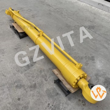
PC300-7 PC350-7 PC360-7 Arm Cylinder Assembly S...
2025-12-11
Arm extension and retraction – Primary function for moving the arm.
Digging force application – Generates force for digging and pulling material.
Load control – Manages the weight and position of the bucket and load.
Reach control – Determines the horizontal reach distance of the bucket.
Digging depth control – Controls the vertical depth of the bucket during digging.
Trenching operation – Essential for precise trench digging and profiling.
Lifting assist – Assists the boom in lifting operations by positioning the load.
Grade finishing – Provides fine control for final grading and leveling.
Crowd force generation – Creates the inward (crowd) force for loading.
Load positioning – Precisely positions the bucket for dumping or placing material.
Reach adjustment – Adjusts the working radius without moving the machine.
Parallel crowd function – Maintains bucket angle during arm movement (if equipped).
Breakout force contribution – A major source of the machine's breakout force.
Arm float function – Allows the arm to follow ground contours (with control valve).
Stability adjustment – Shifts the machine's center of gravity during operation.
Shock absorption – Hydraulic cushions absorb shocks from digging impacts.
Precise movement control – Enables smooth and accurate arm operation.
Cycle time optimization – Fast arm movement speeds up digging cycles.
Material handling – Used in lifting and placing pipes, rocks, or other objects.
Slope working adaptation – Adjusts arm angle for working on slopes.
Truck loading efficiency – Positions bucket accurately over trucks for loading.
Ditch cleaning – Extends and retracts for cleaning and shaping ditches.
Foundation work – Essential for excavating foundations and footings.
Demolition assistance – Positions bucket or attachment for demolition tasks.
Pressure holding – Holds position against load when controls are neutral.
Safety function &ndash– Maintains arm position in case of hydraulic system failure.
Operator control feedback – Provides feel and resistance for precise operation.
Power mode implementation – Hydraulic flow/pressure affects its speed and force.
Attachment compatibility – Works with various attachments (grapple, hammer, etc.).
Overall productivity determinant – Its power and speed are key to machine output.
16
view
detail
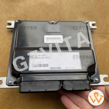
Excavator Part PC300-8MO PC360-8MO Pump Control...
2025-12-11
Central processing unit (CPU) – Executes control algorithms and logic.
Sensor signal acquisition – Collects data from all machine sensors.
Analog-to-digital conversion – Converts sensor analog signals to digital values.
Input signal conditioning – Filters and scales raw sensor inputs.
Controller Area Network (CAN) management – Manages high-speed data bus communication.
J1939 protocol implementation – Standardized communication for engine and components.
Hydraulic pump control – Calculates and outputs commands to pump regulators.
Engine ECU communication – Exchanges data with engine control unit for power management.
Load sensing system processing – Calculates hydraulic demand and optimizes pump flow.
Operator command interpretation – Processes joystick, pedal, and switch inputs.
Power mode logic – Implements Eco, Standard, and Power mode algorithms.
Work mode selection – Controls patterns like Digging, Lifting, etc.
Closed-loop control – Compares target and actual values (e.g., pressure, speed) for adjustment.
Fault detection and diagnosis (FDD) – Monitors system parameters for abnormalities.
Diagnostic Trouble Code (DTC) storage – Logs fault codes and freeze frame data.
Warning and alert generation – Activates visual/audible alarms for operators.
Data logging – Records operational data (hours, fuel, events) for analysis.
Immobilizer function – Interfaces with security systems to enable/disable machine.
Parameter customization – Allows authorized adjustment of machine settings.
Display driver – Generates graphics and data for the monitor screen.
Keypad/interface management – Processes inputs from the operator's control panel.
Attachment control logic – Manages optional hydraulic attachments.
Pump torque limiting – Prevents engine stall by limiting hydraulic power demand.
Engine speed governing – Sends desired RPM signals to the engine ECU.
Auto-idle function – Lowers engine speed when controls are neutral.
Grade assist logic (if equipped) – Calculates and maintains blade or boom angle.
Safety interlock processing – Enables functions only when conditions are safe (e.g., seat switch).
Software-based calibration – Stores calibration data for sensors and actuators.
Fail-safe strategy execution – Limits machine function to a safe state upon critical faults.
System integration hub – Acts as the primary coordinator for all electronic subsystems.